Tag Archives: speed gearboxes

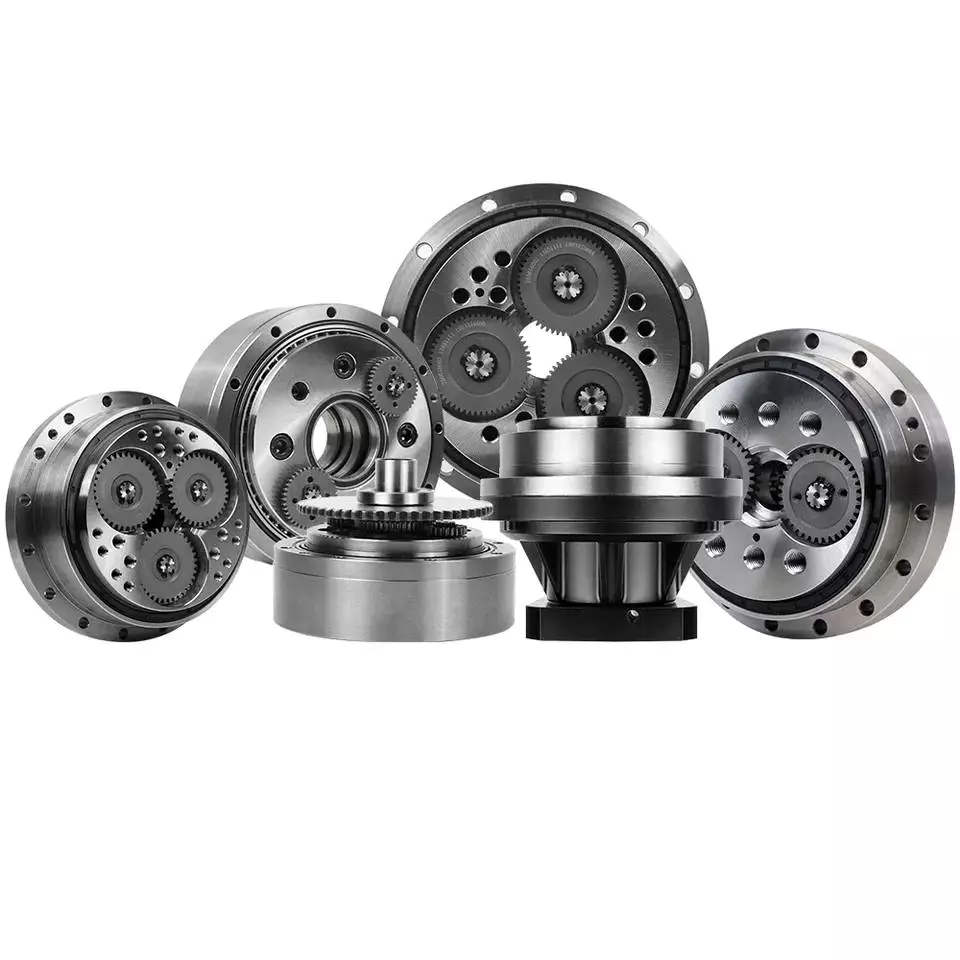
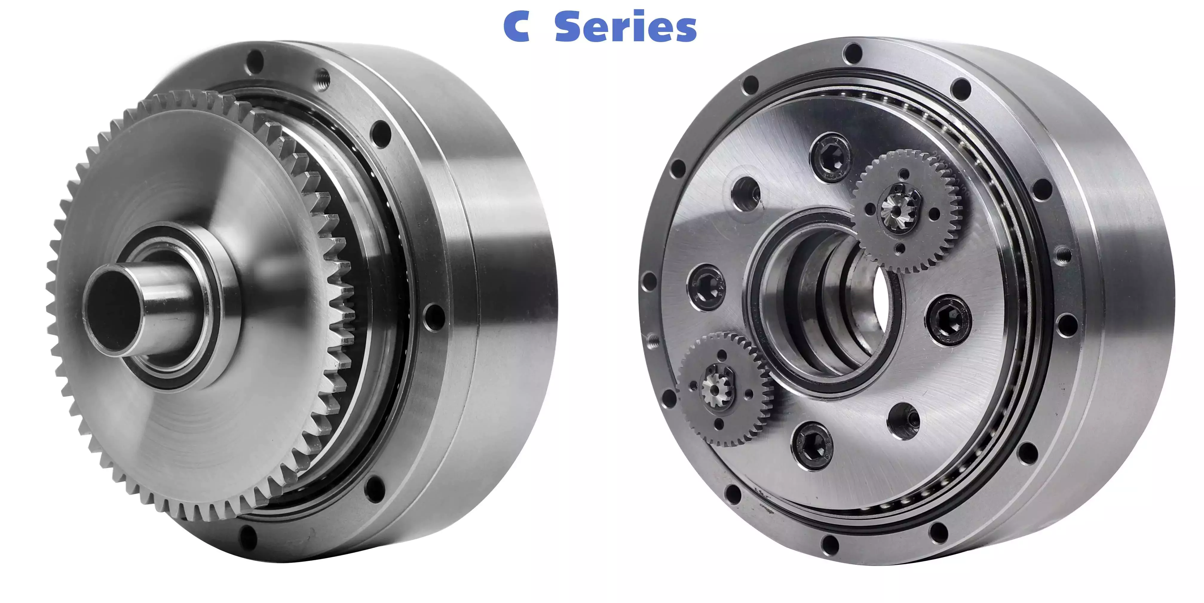
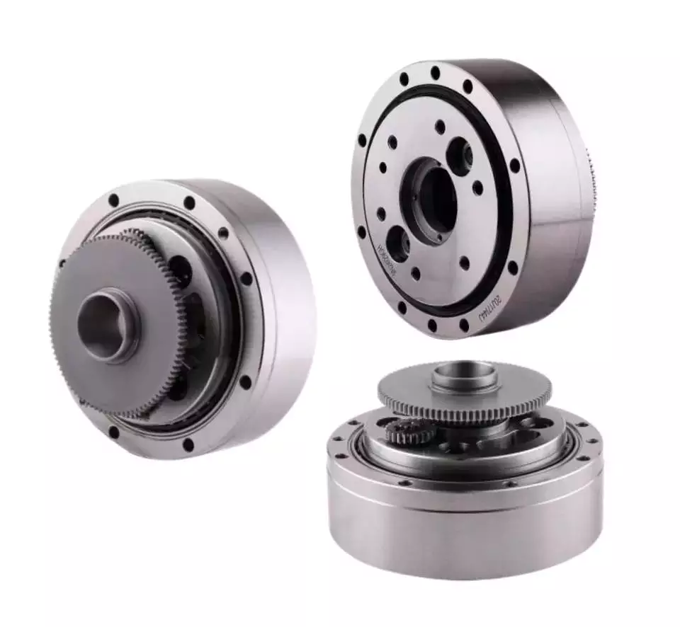
China Custom Micro Planetary Reducer Ratio 3: 1-1200: 1, Powder Metallurgy Machinery Gear Reducer Speed Transmission High Torque Precision Gearboxes for DC Motors manufacturer

Product Description

We are 1 of the top manufacturer of planetary gearboxes through powder metallurgy. A gearbox is a energy transmission unit to make high torque by lowering the travel velocity or improve the travel pace the other way. Planetary gearbox consisting 3 components: sunshine gear, planet gear and ring equipment . A Solar gear is a gearwheel in a planetary equipment method, that rotates all around its possess axis and has other gears (earth gears) that rotate about it. Considerably like the Solar and planets in our photo voltaic system. The amount of planetary gears in a gearbox differs based mostly on the equipment ratio. Most planetary gearboxes have from 2 to 5 world gears.
When hunting at planetary gears, the toughness of the gearbox is usually determined by the dimensions of the sun gear. Bigger solar gears will enable for increased torque values. The world provider,Its goal is to maintain up to gears of the very same size, which mesh with the sunshine gear.


Planetary Gearbox benefits:

  1. Gives large torque at gradual speeds .
  2. The shafts are made up of hardened and tempered alloy steel .
  3. Solar gears ,earth gears and ring gears are produced of powder metallurgy and sintering metal
  4. Lower sounds ranges.
  5. Great good quality taper roller bearings for input and output shafts .
  6. Substantial efficiency .

We create precision steel gearboxes by way of powder metallurgy .
Powder metallurgy is a metal working process in which finely-powdered metal is blended with binder materials to produce a”feedstock” that is then shaped and solidified using injection molding.The ability to combine a number of functions into 1 process ensures MIM is profitable in saving guide occasions as well as fees, offering considerable benefits to producers. The metallic injection molding process may possibly be a eco-friendly engineering thanks to the significant reduction in wastage in contrast to “classic” producing methods.

MIM can make elements exactly where it is challenging, or even extremely hard, to successfully manufacture an merchandise via other means of fabrication. Enhanced costs for traditional production methods inherent to portion complexity, such as inner/exterior threads, miniaturization, or identification marking, usually do not boost the cost in a MIM operation thanks to the overall flexibility of injection molding.
The window of economic gain in steel injection molded parts lies in complexity and volume for little-measurement components. MIM resources are comparable to metallic fashioned by competing approaches, and ultimate items are used in a wide variety of industrial, commercial, healthcare, dental, firearms, aerospace, and automotive applications. Dimensional tolerances of ±0.3% are widespread and machining is essential for closer tolerances .
MIM technology has identified elevated purposes in the industrial globe – from home appliances to watches, cars to aerospace, and health-related to orthodontics.

The positive aspects of metal injection molding for steel fabrications :

  • Optimum degree of design independence for complex designs and geometries
  • Provides functional economic solutions to more and more stringent materials and solution style specifications
  • Useful integration of a variety of features, this kind of as lateral drillings, interior and exterior threads and gear tooth.
  • Factors can be warmth and surface area handled, plated, welded and soldered
  • Very high volume production sequence operate on fully-computerized injection molding equipment employing multi-cavity instruments


Steel injection moulding method custom made steel parts 

MIM prcess in each steps :
one. Steel powers option
2. Binders
three. Mixing
4. Molding
5. De-binding
six. Sintering
7. put up sintering procedure such as polishing 
eight. Mechanical homes MIM parts

Custom-made metallic components specification
 

Product sort Personalized large precision little gearboxes for DC motors
Material steel 
Process Powder metallurgy , steel injection molding 
Therapy plating ,sand blasting , PVD , coating
Tolerance ±0.3%
Drawing format DWG ,IGS , STP
Supply time  20 times for mass manufacturing

Custom metallic areas

Workshop

US $3
/ Piece
|
2,000 Pieces

(Min. Order)

###

Application: Motor, Electric Cars, Motorcycle, Machinery, Marine, Toy, Agricultural Machinery, Car, Car Parts
Function: Distribution Power, Clutch, Change Drive Torque, Change Drive Direction, Speed Changing, Speed Reduction, Speed Increase
Layout: Cycloidal
Hardness: Hardened Tooth Surface
Installation: Horizontal Type
Step: Three-Step

###

Samples:
US$ 5/Piece
1 Piece(Min.Order)

|
Request Sample

###

Customization:

###

Product type Custom high precision small gearboxes for DC motors
Material steel 
Process Powder metallurgy , metal injection molding 
Treatment plating ,sand blasting , PVD , coating
Tolerance ±0.3%
Drawing format DWG ,IGS , STP
Delivery time  20 days for mass production

The Advantages of Using a Cyclone Gearbox

Using a cycloidal gearbox to drive an input shaft is a very effective way to reduce the speed of a machine. It does this by reducing the speed of the input shaft by a predetermined ratio. It is capable of very high ratios in relatively small sizes.helical gearbox

Transmission ratio

Whether you’re building a marine propulsion system or a pump for the oil and gas industry, there are certain advantages to using cycloidal gearboxes. Compared to other gearbox types, they’re shorter and have better torque density. These gearboxes also offer the best weight and positioning accuracy.
The basic design of a cycloidal gearbox is similar to that of a planetary gearbox. The main difference is in the profile of the gear teeth.
Cycloid gears have less tooth flank wear and lower Hertzian contact stress. They also have lower friction and torsional stiffness. These advantages make them ideal for applications that involve heavy loads or high-speed drives. They’re also good for high gear ratios.
In a cycloidal gearbox, the input shaft drives an eccentric bearing, while the output shaft drives the cycloidal disc. The cycloidal disc rotates around a fixed ring, and the pins of the ring gear engage the holes in the disc. The pins then drive the output shaft as the disc rotates.
Cycloid gears are ideal for applications that require high gear ratios and low friction. They’re also good for applications that require high torsional stiffness and shock load resistance. They’re also suitable for applications that require a compact design and low backlash.
The transmission ratio of a cycloidal gearbox is determined by the number of lobes on the cycloidal disc. The n=n design of the cycloidal disc moves one lobe per revolution of the input shaft.
Cycloid gears can be manufactured to reduce the gear ratio from 30:1 to 300:1. These gears are suitable for high-end applications, especially in the automation industry. They also offer the best positioning accuracy and backlash. However, they require special manufacturing processes and require non-standard characteristics.

Compressive force

Compared with conventional gearboxes, the cycloidal gearbox has a unique set of kinematics. It has an eccentric bearing in a rotating frame, which drives the cycloidal disc. It is characterized by low backlash and torsional stiffness, which enables geared motion.
In this study, the effects of design parameters were investigated to develop the optimal design of a cycloidal reducer. Three main rolling nodes were studied: a cycloidal disc, an outer race and the input shaft. These were used to analyze the motion related dynamic forces, which can be used to calculate stresses and strains. The gear mesh frequency was calculated using a formula, which incorporated a correction factor for the rotating frame of the outer race.
A three-dimensional finite element analysis (FEA) study was conducted to evaluate the cycloidal disc. The effects of the size of the holes on the disc’s induced stresses were investigated. The study also looked at the torque ripple of a cycloidal drive.
The authors of this study also explored backlash distribution in the output mechanism, which took into account the machining deviations and structure and geometry of the output mechanism. The study also looked at the relative efficiency of a cycloidal reducer, which was based on a single disc cycloidal reducer with a one-tooth difference.
The authors of this study were able to deduce the contact stress of the cycloidal disc, which is calculated using the material-based contact stiffness. This can be used to determine accurate contact stresses in a cycloidal gearbox.
It is important to know the ratios needed for calculation of the bearing rate. This can be calculated using the formula f = k (S x R) where S is the volume of the element, R is the mass, k is the contact stiffness and f is the force vector.helical gearbox

Rotational direction

Unlike the conventional ring gear which has a single axis of rotation, cycloidal gearbox has three rotational axes which are parallel and are located in a single plane. A cycloidal gearbox has excellent torsional stiffness and shock load capacity. It also ensures constant angular velocity, and is used in high-speed gearbox applications.
A cycloidal gearbox consists of an input shaft, a drive member and a cycloidal disc. The disc rotates in one direction, while the input shaft rotates in the opposite direction. The input shaft eccentrically mounts to the drive member. The cycloidal disc meshes with the ring-gear housing, and the rotational motion of the cycloidal disc is transferred to the output shaft.
To calculate the rotational direction of a cycloidal gearbox, the cycloid must have the correct angular orientation and the centerline of the cycloid should be aligned with the center of the output hole. The cycloid’s shortest length should be equal to the radius of the pin circle. The cycloid’s largest radius should be the size of the bearing’s exterior diameter.
A single-stage gear will not have much space to work with, so you’ll need a multistage gear to maximize space. This is also the reason that cycloid gears are usually designed with a shortened cycloid.
To calculate the most efficient tooth profile for a cycloidal gear, a new method was devised. This method uses a mathematical model that uses the cycloid’s rotational direction and a few other geometric parameters. Using a piecewise function related to the distribution of pressure angle, the cycloid’s most efficient profile is determined. It is then superimposed on the theoretical profile. The new method is much more flexible than the conventional method, and can adapt to changing trends of the cycloidal profile.

Design

Several designs of cycloidal gearboxes have been developed. These gearboxes have a large reduction ratio in one stage. They are mainly used for heavy machines. They provide good torsional stiffness and shock load capacity. However, they also have vibrations at high RPM. Several studies have been conducted to find a solution to this problem.
A cycloidal gearbox is designed by calculating the reduction ratio of a mechanism. This ratio is obtained by the size of the input speed. This is then multiplied by the reduction ratio of the gear profile.
The most important factor in the design of a cycloidal gearbox is the load distribution along the width of the gear. Using this as a design criterion, the amplitude of vibration can be reduced. This will ensure that the gearbox is working properly. In order to generate proper mating conditions, the trochoidal profile on the cycloidal disc periphery must be defined accurately.
One of the most common forms of cycloidal gears is circular arc toothing. This is the most common type of toothing used today.
Another form of gear is the hypocycloid. This form requires the rolling circle diameter to be equal to half the base circle diameter. Another special case is the point tooth form. This form is also called clock toothing.
In order to make this gear profile work, the initial point of contact must remain fixed to the edge of the rolling disk. This will generate the hypocycloid curve. The curve is traced from this initial point.
To investigate this gear profile, the authors used a 3D finite element analysis. They used the mathematical model of gear manufacturing that included kinematics parameters, output moment calculations, and machining steps. The resulting design eliminated backlash.helical gearbox

Sizing and selection

Choosing a gearbox can be a complex task. There are many factors that need to be taken into account. You need to determine the type of application, the required speed, the load, and the ratio of the gearbox. By gaining this information, you can find a solution that works best for you.
The first thing you need to do is find the proper size. There are several sizing programs available to help you determine the best gearbox for your application. You can start by drawing a cycloidal gear to help you create the part.
During sizing, it is important to consider the environment. Shock loads, environmental conditions, and ambient temperatures can increase wear on the gear teeth. The temperature also has a significant impact on lubrication viscosities and seal materials.
You also need to consider the input and output speed. This is because the input speed will change your gearbox ratio calculations. If you exceed the input speed, you can damage the seals and cause premature wear on the shaft bearings.
Another important aspect of sizing is the service factor. This factor determines the amount of torque the gearbox can handle. The service factor can be as low as 1.4, which is sufficient for most industrial applications. However, high shock loads and impact loads will require higher service factors. Failure to account for these factors can lead to broken shafts and damaged bearings.
The output style is also important. You need to determine if you want a keyless or keyed hollow bore, as well as if you need an output flange. If you choose a keyless hollow bore, you will need to select a seal material that can withstand the higher temperatures.
China Custom Micro Planetary Reducer Ratio 3: 1-1200: 1, Powder Metallurgy Machinery Gear Reducer Speed Transmission High Torque Precision Gearboxes for DC Motors     manufacturer China Custom Micro Planetary Reducer Ratio 3: 1-1200: 1, Powder Metallurgy Machinery Gear Reducer Speed Transmission High Torque Precision Gearboxes for DC Motors     manufacturer
editor by czh 2023-01-25

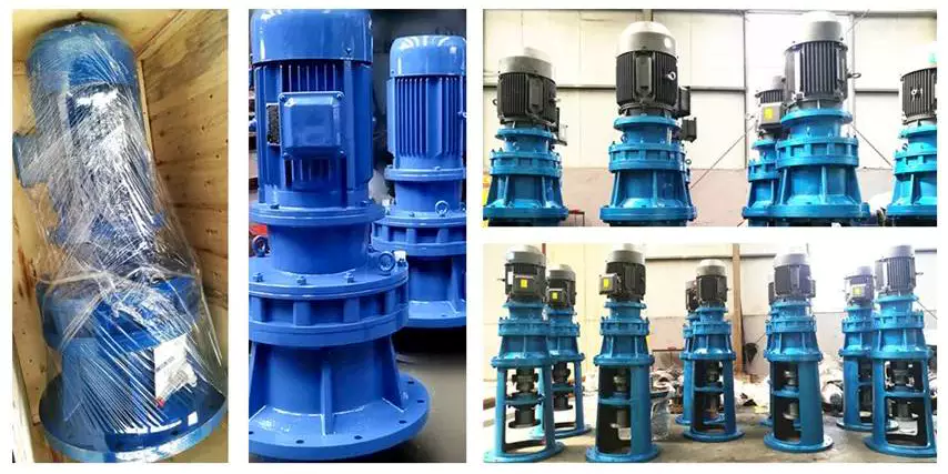
China Cycloidal Gearbox Cyclo Gear Box Drive Motor Speed Reducer Gearboxes Planetary Sumitomo Power Industrial Transmission Best Price Manufacture Cycloidal Gearbox cycloidal gearbox ratio

Merchandise Description

Cycloidal gearbox cyclo gear box travel motor velocity reducer gearboxes planetary sumitomo energy industrial transmission greatest price tag manufacture Cycloidal gearbox

X / B series higher good quality cycloidal gearbox small planetary reducer

Swift Specifics:

Type: XB sequence Cycloidal Pin Wheel Speed Reducer    

Input Velocity: one thousand-1500rmp   

Output Pace: .3-280rpm

Certification: ISO9001 CE          

Ex Electrical power:.09-132KW                  

Guarantee: 1Years

Item Title  X/B sequence Cycloidal Pin Wheel Pace Reducer
The Gear Substance GCR15
The circumstance Materials Cast Iron
Shade Blue,Inexperienced, or Customized
HS Code 84834090
Design X3
Delivery time seven-10days
Model TIANGOU


Application: Motor, Machinery, Agricultural Machinery
Function: Distribution Power, Speed Reduction, Speed Increase
Layout: Cycloidal
Hardness: Hardened Tooth Surface
Installation: Vertical Type
Step: Stepless

###

Samples:
US$ 9999/Piece
1 Piece(Min.Order)

|
Request Sample

###

Product Name  X/B series Cycloidal Pin Wheel Speed Reducer
The Gear Material GCR15
The case Material Cast Iron
Color Blue,Green, or Customized
HS Code 84834090
Model X3
Delivery time 7-10days
Brand TIANGOU

How to Calculate Transmission Ratio for a Cycloidal Gearbox

Using a cycloidal gearbox can be very useful in a wide variety of situations. However, it’s important to understand how to use it properly before implementing it. This article discusses the benefits of using a cycloidal gearbox, how to calculate the transmission ratio, and how to determine the effects of dynamic and inertial forces on the gearbox.helical gearbox

Dynamic and inertial effects

Various studies have been done to study the dynamic and inertial effects of cycloidal gearboxes. These studies have been performed using numerical, analytical and experimental methods. Depending on the nature of the load and its distribution along the gear, a variety of models have been developed. These models use finite element method to determine accurate contact stresses. Some of these models have been developed to address the nonlinear elasticity of contacts.
Inertial imbalance in a cycloidal gearbox causes vibration and can affect the efficiency of the device. This can increase mechanical losses and increase wear and tear. The efficiency of the device also depends on the torque applied to the cycloidal disk. The effectiveness of the device increases as the load increases. Similarly, the nonlinear contact dynamics are also associated with an increase in efficiency.
A new model of a cycloidal reducer has been developed to predict the effects of several operational conditions. The model is based on rigid body dynamics and uses a non-linear stiffness coefficient. The model has been validated through numerical and analytical methods. The model offers drastic reduction in computational costs. The model allows for a quick analysis of several operational conditions.
The main contribution of the paper is the investigation of the load distribution on the cycloidal disc. The study of this aspect is important because it allows for an analysis of the rotating parts and stresses. It also provides an indication of which gear profiles are best suited for optimizing torque transmission. The study has been conducted with a variety of cycloidal gearboxes and is useful in determining the performance of different types of cycloidal gearboxes.
To study the load distribution on the cycloidal disc, the authors investigated the relationship between contact force, cycloidal gearboxes and different gear profiles. They found that the non-linear contact dynamics have a large impact on the efficiency of a cycloidal gearbox. The cycloidal gearbox is an ideal solution for applications that involve highly dynamic servos. It can also be used in machine tool applications and food processing industries.
The study found that there are three common design principles of cycloidal reducers. These are the contact force distribution, the speed reduction and the trochoidal profile of the cycloidal disc. The trochoidal profile has to be defined carefully to ensure correct mating of the rotating parts. The trochoidal profile provides an indication of which gear profiles are best for optimizing torque transmission. The contact force distribution can be improved by refining the mesh along the disc’s width.
As the input speed increases, the efficiency of the reducer increases. This is because contact forces are constantly changing in magnitude and orientation. A cycloidal reducer with a one tooth difference can reduce input speed by up to 87:1 in a single stage. It also has the ability to handle high-cycle moves without backlash.helical gearbox

Transmission ratio calculation

Getting the correct transmission ratio calculation for a cycloidal gearbox requires a good understanding of what a gearbox is, as well as the product that it is being used for. The correct ratio is calculated by dividing the output speed of the output gear by the input speed of the input gear. This is usually accomplished by using a stopwatch. In some cases, a catalog or product specification may be required. The correct ratio is determined by a combination of factors, such as the amount of torque applied to the mechanism, as well as the size of the gears involved.
A cycloidal gear is a type of gear tooth profile that can be represented using a spline. It is also possible to model a gear with a cycloidal profile by using a spline to connect points against the beginning of a coordinate system. This is important in the design and functionality of a gear.
There are many different gears used in machines and devices. These include the herringbone gear, the helical gear and the spiral bevel gear. The best transmission ratios are typically obtained with a cycloidal gearbox. In addition to ensuring the accuracy of positioning, a cycloidal gearbox provides excellent backlash. Cycloid gears have a high degree of mechanical efficiency, low friction, and minimal moment of inertia.
A cycloidal gearbox is often referred to as a planetary gearbox, though it is technically a single-stage gearbox. In addition to having a ring gear, the gearbox has an eccentric bearing that drives the cycloidal disc in an eccentric rotation. This makes the cycloidal gearbox a good choice for high gear ratios in compact designs.
The cycloid disc is the key element of a cycloidal gearbox. The cycloid disc has n=9 lobes, and each lobe of the disc moves by a lobe for every revolution of the drive shaft. The cycloid disc is then geared to a stationary ring gear. The cycloidal disc’s lobes act like teeth on the stationary ring gear.
There are many different gears that are classified by the profile of the gear teeth. The most common gears are the involute and helical gears. Most motion control gears include spur designs. However, there are many other types of gears that are used in various applications. The cycloidal gear is one of the more complicated gears to design. The cycloid disc’s outline can be represented using markers or smooth lines, though a scatter chart will also do.
The cycloid disc’s lobes rotate on a reference pitch circle of pins. These pins rotate 40 deg during the eccentric rotation of the drive shaft. The pins rotate around the disc to achieve a steady rotation of the output shaft.
The cycloid disc’s other obvious, and possibly more important, feature is the’magic’ number of pins. This is the number of pins that protrude through the face of the disc. The disc has holes that are larger than the pins. This allows the pins to protrude through the disc and attach to the output shaft.helical gearbox

Application

Whether you’re building a robot drive or you’re simply looking for a gearbox to reduce the speed of your vehicle, a cycloidal gearbox is a great way to achieve a high reduction ratio. Cycloidal gearboxes are a low-friction, lightweight design that has an extremely stable transmission. They are suitable for industrial robots and can be used in many applications, including positioning robots.
Cycloidal gearboxes reduce speed by using eccentric motion. The eccentric motion enables the entire internal gear to rotate in wobbly cycloidal motion, which is then translated back into circular rotation. This eliminates the need for stacking gear stages. Cycloidal gearboxes also have less friction, higher strength, and greater durability than conventional gearboxes.
The cycloidal gearbox is also used in a number of applications, including marine propulsion systems, and robot drives. Cycloidal gearboxes reduce vibration by using offset gearing to cancel out vibrations.
Cycloidal gears have lower friction, higher strength, and better torsional stiffness than involute gears. They also have a reduced Hertzian contact stress, making them better than involute gears for use with shock loads. They also have a smaller size and weight than conventional gearboxes, and they have a higher reduction ratio than involute gears.
Cycloidal gears are typically used to reduce the speed of motors, but they also offer a number of other advantages. Cycloidal gearboxes have a smaller footprint than other gearboxes, allowing them to fit into confined spaces. They also have low backlash, allowing for precise movement. Cycloidal gears have a higher efficiency, resulting in lower power requirements and lower wear.
The cycloidal disc is one of the most important components of the gearbox. Cycloidal discs are normally designed with a short cycloid, which minimizes the eccentricity of the disc. They are also designed with a shortened flank, resulting in better strength and less stress concentration. Cycloidal discs are typically geared to a stationary ring gear. The cycloid is designed to roll around the stationary ring pins, which push against the circular holes in the disc. Cycloidal gearboxes typically employ two degrees of shift.
Cycloidal drives are ideal for heavy load applications. They also have high torsional stiffness, which makes them highly resistant to shock loads. Cycloidal drives also offer a high reduction ratio, which can be achieved without the need for a large input shaft. They are also compact and have a high service life.
The output shaft of a cycloidal gearbox always has two degrees of shifting, which ensures that the input and output shafts always rotate at a different speed. The output shaft would be a pin casing around the drive disks, which would also allow for easy maintenance.
Cycloidal gearboxes are also very compact and lightweight, so they are ideal for use in industrial robots. The cycloidal gearbox reducer is the most stable, low-vibration reducer in industrial robots, and it has a wide transmission ratio range.
China Cycloidal Gearbox Cyclo Gear Box Drive Motor Speed Reducer Gearboxes Planetary Sumitomo Power Industrial Transmission Best Price Manufacture Cycloidal Gearbox     cycloidal gearbox ratioChina Cycloidal Gearbox Cyclo Gear Box Drive Motor Speed Reducer Gearboxes Planetary Sumitomo Power Industrial Transmission Best Price Manufacture Cycloidal Gearbox     cycloidal gearbox ratio
editor by czh 2023-01-13

China Wholesale Speed Reducer Gearbox Motor Gearboxes for Medical Equipment precision cycloidal gearbox

Solution Description

Wholesale Velocity Reducer Gearbox Motor Gearboxes for Health care Equipment 

Our helical agricultural gearbox has many things for your picking and we can create as per your drawing or sample to fulfill your specific request
one. Massive output torque
2. Safe, dependable, cost-effective and resilient
3. Secure transmission, tranquil procedure
4. Higher carrying capability
five. Large modularization design, may equip with various outer power input conveniently. Identical device sort may possibly equip with a variety of electrical power motor. It is straightforward to recognize the combination and junction among each and every equipment kind
six. Transmission ratio: Fine division, wide scope. The mixed device sort may form quite massive transmission ratio, i. E. Output extremely minimal rotary speed.
seven. Type of installation: The situation to be put in is not minimal.
eight. High strength, compact the box physique of large strength solid iron, equipment and equipment shaft adapts the gasoline carbonization, quenching and fantastic grinding method, therefore the bearing potential of unit quantity is higher.
nine. Prolonged daily life: Below the issue of appropriate sort selected(such as choosing appropriate operation parament ) standard operation and servicing, the life if primary areas velocity reducer(apart from putting on components)must not be less than 20000 hrs. The donning components incorporate lubricating oil, oil seal and bearing.
ten. Reduced noise: Since main areas of velocity reducer are processed, and examined critically, as a result the sound of pace reducer is low.
11. Parallel axis-bevel wheel velocity-down motor.
See the underneath attributes:
Measurement: 40mm—160mm
Reduction ratio: 3 — 512
Torque transmission: 5 Nm — 8 95 Nm
Precision backlash: ≤ 5arcmin
Running sound: fifty one 70 dB (A)
You are welcome to ship us element enquiry by e-mail or fax.
We can also provide Gearbox, agricultural gearbox, planetary gearbox, worm gearbox, flender gearbox, maritime gearbox, gearbox, reduction gearbox, transmission gearbox, gearbox, mower gearbox, rotary cutter gearbox, modest transmission gearbox, gearbox for conveyor, bevel gearbox, helical gearbox, swing gearbox, variable speed gearbox, differential gearbox, little planetary gearbox, reducer gearbox, tiller gearbox, pto gearbox, gearbox reducer, hollow shaft gearbox, pace reduction gearbox, industrial gearbox, planetary reduction gearbox, lawn mower gearbox, rotary tiller gearbox, gearbox transmission, worm reduction gearbox, aluminum gearbox, forklift gearbox, nmrv 075 worm gearbox, nmrv030 worm gearbox, shaft mounted gearbox, nmrv 050 worm gearbox, gearbox for agricultural equipment, energy tiller gearbox, handbook worm gearbox, spiral bevel gearbox, nmrv gearbox, worm wheel gearbox, decrease velocity gearbox, industrial transmission gearbox, worm reducer gearbox, gearbox rpm reducer, helical gearbox reducer, wheel planetary gearbox, nmrv040 worm gearbox, worm gearbox reducer, nmrv worm gearbox, aluminium worm gearbox, gearbox reduction, rv collection worm gearbox, worm pace gearbox, nmrv050 worm gearbox, gear reducer, worm equipment reducer, helical gear reducer, gear velocity reducer, worm equipment speed reducer, shaft mounted equipment reducer, planetary gear reducer, helical equipment speed reducer, worm gear wheel reducer, pace gear reducer, bevel gear reducer, planetary gear velocity reducer, spur equipment reducer, aluminum worm gear reduce, nmrv worm gear reducers, helical-worm gear reducer, helical bevel gear reducers, substantial pace gear reducer, gear speed reducers, industrial gear reducer, higher torque equipment reducers

HangZhou CZPT Market Co., Ltd. is a specialized supplier of a complete range of chains, sprockets, gears, equipment racks, v belt pulley, timing pulley, V-belts, couplings, machined parts and so on.

Owing to our sincerity in offering ideal services to our customers, understanding of your needs and overriding perception of accountability toward filling buying demands, we have attained the have faith in of purchasers around the world. Having accrued treasured encounter in cooperating with overseas clients, our goods are offering well in the American, European, South American and Asian marketplaces. Our merchandise are produced by modern computerized equipment and products. In the meantime, our merchandise are created in accordance to high top quality expectations, and complying with the worldwide superior normal requirements.

With many years’ expertise in this line, we will be trustworthy by our benefits in aggressive cost, 1-time delivery, prompt reaction, on-hand engineering help and very good right after-product sales companies.

In addition, all our production procedures are in compliance with ISO9001 requirements. We also can design and style and make non-regular items to meet up with customers’ particular needs. Good quality and credit score are the bases that make a corporation alive. We will give ideal solutions and substantial quality merchandise with all sincerity. If you want any info or samples, please contact us and you will have our quickly reply.

FAQ:
Q1: Are you buying and selling business or manufacturer ?
A: We are manufacturing facility.

Q2: How lengthy is your shipping time and shipment?
1.Sample Direct-instances: generally 10 workdays.
two.Production Direct-instances: twenty-forty workdays right after acquiring your deposit.

Q3. What is your terms of payment?
A: T/T thirty% as deposit, and 70% just before delivery.

This autumn: What is your rewards?
1. Company,the most competitive price and great high quality.
2. Excellent complex engineers give you the ideal help.
three. OEM is available.
four. Rich stock and fast delivery.

Q5. If you can not discover the product on our web site,what do you next?
You should deliver us inquiry with product photos and drawings by e mail or other ways and we are going to check.


US $90-120
/ Piece
|
100 Pieces

(Min. Order)

###

Shipping Cost:

Estimated freight per unit.


To be negotiated|


Freight Cost Calculator

###

Application: Motor, Electric Cars, Motorcycle, Machinery, Marine, Agricultural Machinery
Function: Distribution Power, Clutch, Change Drive Torque, Change Drive Direction, Speed Changing, Speed Reduction
Layout: Cycloidal

###

Samples:
US$ 120/Piece
1 Piece(Min.Order)

|

Order Sample

###

Customization:

The Basics of a Cyclone Gearbox

Besides being compact, cycloidal speed reducers also offer low backlash and high ratios. Because of the small size of the drive, they are ideal for applications where space is a problem.helical gearbox

Involute gear tooth profile

Almost all gears use an involute gear tooth profile. This profile has a single curve, which means that the gear teeth do not have to be aligned closely with each other. This profile is smooth and can be manufactured easily.
Cycloid gears have a combination of epicycloid and hypocycloid curves. This makes them stronger than involute gear teeth. However, they can be more expensive to manufacture. They also have larger reduction ratios. They transmit more power than involute gears. Cycloid gears can be found in clocks.
When designing a gear, you need to consider several factors. Some of these include the number of teeth, the tooth angle and the lubrication type. Having a gear tooth that is not perfectly aligned can result in transmission error, noise and vibration.
The tooth profile of an involute gear is usually considered the best. Because of this, it is used in a wide variety of gears. Some of the most common applications for this profile are power transmission gears. However, this profile is not the best for every application.
Cycloid gears require more complex manufacturing processes than involute gear teeth. This can cause a larger tooth cost. Cycloid gears are used for less noisy applications.
Cycloid gears also transmit more power than involute gears. This can cause problems if the radii change tangentially. However, the shape is more simple than involute gears. Involute gears can handle centre sifts better.
Cycloid gears are less susceptible to transmission error. Cycloid gears have a convex surface, which makes them stronger than involute teeth. Cycloid gears also have a larger reduction ratio than involute gears. Cycloid teeth do not interfere with the mating teeth. However, they have a smaller number of teeth than involute teeth.

Rotation on the inside of the reference pitch circle of the pins

Whether a cycloidal gearbox is designed for stationary or rotating applications, the fundamental law of gearing must be observed: The ratio of angular velocities must be constant. This requires the rotation on the inside of the reference pitch circle of the pins to be constant. This is achieved through a series of cycloidal teeth, which act like tiny levers to transmit motion.
A cycloidal disc has N lobes which are rotated by three lobes per rotation around N pins. The number of lobes on a cycloidal disc is a significant factor in determining the transmission ratio.
A cycloidal disc is driven by an eccentric input shaft which is mounted to an eccentric bearing within an output shaft. As the input shaft rotates, the cycloidal disc moves around the pins of the pin disc.
The drive pin rotates at a 40 deg angle while the cycloidal disc rotates on the inside of the reference pitch circle of pins. As the drive pin rotates, it will slow the output motion. This means that the output shaft will complete only three revolutions with the input shaft, as opposed to nine revolutions with the input shaft.
The number of teeth on a cycloidal disc must be small compared to the number of surrounding pins. The disc must also be constructed with an eccentric radius. This will determine the size of the hole which will be required for the pin to fit between the pins.
When the input shaft is turned, the cycloidal disc will rotate on the inside of the reference pitch circle of roller pins. This will then transmit motion to the output shaft. The output shaft is supported by two bearings in an output housing. This design has low wear and torsional stiffness.helical gearbox

Transmission ratio

Choosing the right transmission ratio of cycloidal gearbox isn’t always easy. You might need to know the size of your gearbox before you can make an educated choice. You may also need to refer to the product catalog for guidance. For example, CZPT gearboxes have some unique ratios.
A cycloidal gear reducer is a compact and high-speed torque transmission device that reverses the direction of angular movement of the follower shaft. It consists of an eccentric cam positioned inside a cycloidal disc. Pin rollers on the follower shaft fit into matching holes in the cycloidal disc. In the process, the pins slide around the holes, in response to wobbling motion. The cycloidal disc is also capable of engaging the internal teeth of a ring-gear housing.
A cycloidal gear reducer can be used in a wide variety of applications, including industrial automation, robotics and power transmissions on boats and cranes. A cycloidal gear reducer is ideally suited for heavy duty applications with large payloads. They require specialized manufacturing processes, and are often used in equipment with precise output and high efficiency.
The cycloidal gear reducer is a relatively simple structure, but it does require some special tools. Cycloid gear reducers are also used to transmit torque, which is one of the reasons they are so popular in automation. Using a cycloidal gear reducer is a good choice for applications that require higher efficiency and lower backlash. It is also a good choice for applications where size is a concern. Cycloid gears are also a good choice for applications where high speed and high torque are required.
The transmission ratio of cycloidal gearbox is probably the most important function of a gearbox. You need to know the size of your gearbox and the type of gears it contains in order to make the right choice.

Vibration reduction

Considering the unique dynamics of a cycloidal gearbox, vibration reduction measures are required for a smooth operation. These measures can also help with the detection of faults.
A cycloidal gearbox is a gearbox with an eccentric bearing that rotates the center of the gears. It shares torque load with five outer rollers at any given time. It can be applied in many applications. It is a relatively inexpensive asset. However, if it fails, it can have significant economic impacts.
A typical input/output gearbox consists of a ring plate and two cranks mounted on the input shaft. The ring plate rotates when the input shaft rotates. There are two bearings on the output shaft.
The ring plate is a major noise source because it is not balanced. The cycloidal gear also produces noise when it meshes with the ring plate. This noise is generated by structural resonance. Several studies have been performed to solve this problem.
However, there is not much documented work on the condition monitoring of cycloidal gearboxes. In this article, we will introduce modern techniques for vibration diagnostics.
A cycloidal gearbox with a reduced reduction ratio has higher induced stresses in the cycloidal disc. In this case, the size of the output hole is larger and more material is removed from the cycloidal disc. This increase in the disc’s stresses leads to higher vibration amplitudes.
The load distribution along the width of the gear is an important design criterion. Using different gear profiles can help to optimize the transmission of torque. The contact stress of the cycloidal disc can also be investigated.
To determine the amplitude of the noise, the frequency of the gear mesh is multiplied by the shaft rate. If the RPM is relatively stable, the frequency can be used as a measure of magnitude. However, this is only accurate at close to failure.helical gearbox

Comparison with planetary gearboxes

Several differences exist between cycloidal gearboxes and planetary gearboxes. They are related to gear geometry and manufacturing processes. Among them, there are:
– The output shaft of a cycloidal gearbox has a larger torque than the input shaft. The rotational speed of the output shaft is lower than the input shaft.
– The cycloid gear disc rotates at variable velocity, while the planetary gear has a fixed speed. Consequently, the cycloid disc and output flange transmission accuracy is lower than that of the planetary gears.
– The cycloidal gearbox has a larger gripping area than the planetary gear. This is an advantage of the cycloidal gearbox in that it can handle larger loads.
– The cycloid profile has a significant impact on the quality of contact meshing between the tooth surfaces. The width of the contact ellipses increases by 90%. This is a result of the elimination of undercuts of the lobes. In this way, the contact force on the cycloid disc is decreased significantly.
– The cycloid drive has lower backlash and high torsional stiffness. This allows a cycloidal drive to be more stable against shock loads. The cycloid drive is also a compact design, which is ideally suited for applications with large transmission ratios.
– The output hub of the cycloid gearbox has movable pins and rollers. These components are attached to the ring gear in the outer gearbox. The output shaft is also turned by the planet carrier. The output hub of the cycloid system is composed of two parts: the ring gear and the output flange.
– The input shaft of a cycloidal gearbox is connected to a servomotor. The input shaft is a cylindrical element that is fixed to the planet carrier.
China Wholesale Speed Reducer Gearbox Motor Gearboxes for Medical Equipment     precision cycloidal gearboxChina Wholesale Speed Reducer Gearbox Motor Gearboxes for Medical Equipment     precision cycloidal gearbox
editor by czh 2023-01-04