Product Description
Product Description
Zero Defect Gearbox For Tractor Truck 4Wd 4*4
Company Profile
Our Advantages
Exhibition
Packaging & Shipping
FAQ
| Application: | Motor, Electric Cars, Motorcycle, Machinery, Marine, Car |
|---|---|
| Function: | Distribution Power, Change Drive Torque, Change Drive Direction, Speed Changing, Speed Reduction, Speed Increase |
| Layout: | Cycloidal |
| Hardness: | Hardened Tooth Surface |
| Installation: | Torque Arm Type |
| Step: | Four-Step |
| Samples: |
US$ 200/Piece
1 Piece(Min.Order) | |
|---|
| Customization: |
Available
| Customized Request |
|---|
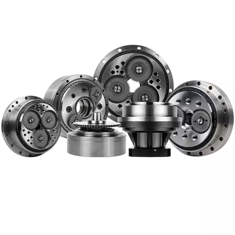
How to Calculate Transmission Ratio for a Cycloidal Gearbox
Using a cycloidal gearbox can be very useful in a wide variety of situations. However, it’s important to understand how to use it properly before implementing it. This article discusses the benefits of using a cycloidal gearbox, how to calculate the transmission ratio, and how to determine the effects of dynamic and inertial forces on the gearbox.
Dynamic and inertial effects
Various studies have been done to study the dynamic and inertial effects of cycloidal gearboxes. These studies have been performed using numerical, analytical and experimental methods. Depending on the nature of the load and its distribution along the gear, a variety of models have been developed. These models use finite element method to determine accurate contact stresses. Some of these models have been developed to address the nonlinear elasticity of contacts.
Inertial imbalance in a cycloidal gearbox causes vibration and can affect the efficiency of the device. This can increase mechanical losses and increase wear and tear. The efficiency of the device also depends on the torque applied to the cycloidal disk. The effectiveness of the device increases as the load increases. Similarly, the nonlinear contact dynamics are also associated with an increase in efficiency.
A new model of a cycloidal reducer has been developed to predict the effects of several operational conditions. The model is based on rigid body dynamics and uses a non-linear stiffness coefficient. The model has been validated through numerical and analytical methods. The model offers drastic reduction in computational costs. The model allows for a quick analysis of several operational conditions.
The main contribution of the paper is the investigation of the load distribution on the cycloidal disc. The study of this aspect is important because it allows for an analysis of the rotating parts and stresses. It also provides an indication of which gear profiles are best suited for optimizing torque transmission. The study has been conducted with a variety of cycloidal gearboxes and is useful in determining the performance of different types of cycloidal gearboxes.
To study the load distribution on the cycloidal disc, the authors investigated the relationship between contact force, cycloidal gearboxes and different gear profiles. They found that the non-linear contact dynamics have a large impact on the efficiency of a cycloidal gearbox. The cycloidal gearbox is an ideal solution for applications that involve highly dynamic servos. It can also be used in machine tool applications and food processing industries.
The study found that there are three common design principles of cycloidal reducers. These are the contact force distribution, the speed reduction and the trochoidal profile of the cycloidal disc. The trochoidal profile has to be defined carefully to ensure correct mating of the rotating parts. The trochoidal profile provides an indication of which gear profiles are best for optimizing torque transmission. The contact force distribution can be improved by refining the mesh along the disc’s width.
As the input speed increases, the efficiency of the reducer increases. This is because contact forces are constantly changing in magnitude and orientation. A cycloidal reducer with a one tooth difference can reduce input speed by up to 87:1 in a single stage. It also has the ability to handle high-cycle moves without backlash.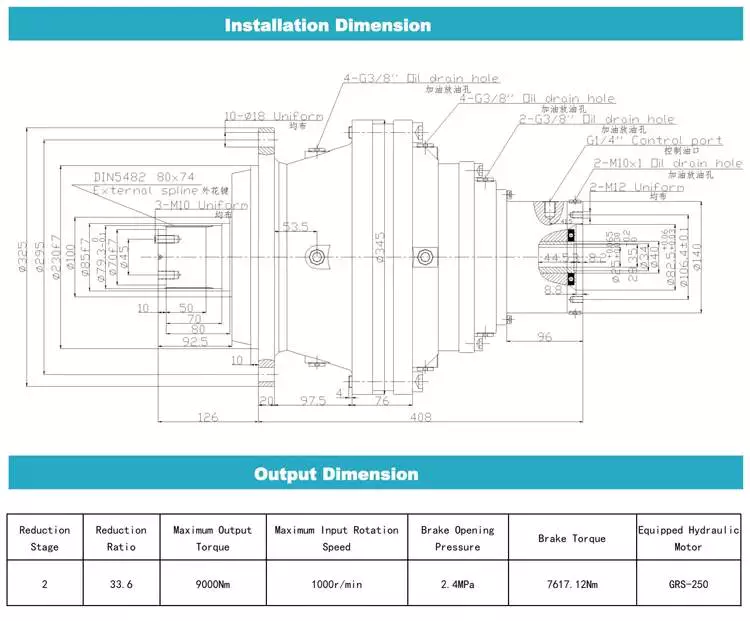
Transmission ratio calculation
Getting the correct transmission ratio calculation for a cycloidal gearbox requires a good understanding of what a gearbox is, as well as the product that it is being used for. The correct ratio is calculated by dividing the output speed of the output gear by the input speed of the input gear. This is usually accomplished by using a stopwatch. In some cases, a catalog or product specification may be required. The correct ratio is determined by a combination of factors, such as the amount of torque applied to the mechanism, as well as the size of the gears involved.
A cycloidal gear is a type of gear tooth profile that can be represented using a spline. It is also possible to model a gear with a cycloidal profile by using a spline to connect points against the beginning of a coordinate system. This is important in the design and functionality of a gear.
There are many different gears used in machines and devices. These include the herringbone gear, the helical gear and the spiral bevel gear. The best transmission ratios are typically obtained with a cycloidal gearbox. In addition to ensuring the accuracy of positioning, a cycloidal gearbox provides excellent backlash. Cycloid gears have a high degree of mechanical efficiency, low friction, and minimal moment of inertia.
A cycloidal gearbox is often referred to as a planetary gearbox, though it is technically a single-stage gearbox. In addition to having a ring gear, the gearbox has an eccentric bearing that drives the cycloidal disc in an eccentric rotation. This makes the cycloidal gearbox a good choice for high gear ratios in compact designs.
The cycloid disc is the key element of a cycloidal gearbox. The cycloid disc has n=9 lobes, and each lobe of the disc moves by a lobe for every revolution of the drive shaft. The cycloid disc is then geared to a stationary ring gear. The cycloidal disc’s lobes act like teeth on the stationary ring gear.
There are many different gears that are classified by the profile of the gear teeth. The most common gears are the involute and helical gears. Most motion control gears include spur designs. However, there are many other types of gears that are used in various applications. The cycloidal gear is one of the more complicated gears to design. The cycloid disc’s outline can be represented using markers or smooth lines, though a scatter chart will also do.
The cycloid disc’s lobes rotate on a reference pitch circle of pins. These pins rotate 40 deg during the eccentric rotation of the drive shaft. The pins rotate around the disc to achieve a steady rotation of the output shaft.
The cycloid disc’s other obvious, and possibly more important, feature is the’magic’ number of pins. This is the number of pins that protrude through the face of the disc. The disc has holes that are larger than the pins. This allows the pins to protrude through the disc and attach to the output shaft.
Application
Whether you’re building a robot drive or you’re simply looking for a gearbox to reduce the speed of your vehicle, a cycloidal gearbox is a great way to achieve a high reduction ratio. Cycloidal gearboxes are a low-friction, lightweight design that has an extremely stable transmission. They are suitable for industrial robots and can be used in many applications, including positioning robots.
Cycloidal gearboxes reduce speed by using eccentric motion. The eccentric motion enables the entire internal gear to rotate in wobbly cycloidal motion, which is then translated back into circular rotation. This eliminates the need for stacking gear stages. Cycloidal gearboxes also have less friction, higher strength, and greater durability than conventional gearboxes.
The cycloidal gearbox is also used in a number of applications, including marine propulsion systems, and robot drives. Cycloidal gearboxes reduce vibration by using offset gearing to cancel out vibrations.
Cycloidal gears have lower friction, higher strength, and better torsional stiffness than involute gears. They also have a reduced Hertzian contact stress, making them better than involute gears for use with shock loads. They also have a smaller size and weight than conventional gearboxes, and they have a higher reduction ratio than involute gears.
Cycloidal gears are typically used to reduce the speed of motors, but they also offer a number of other advantages. Cycloidal gearboxes have a smaller footprint than other gearboxes, allowing them to fit into confined spaces. They also have low backlash, allowing for precise movement. Cycloidal gears have a higher efficiency, resulting in lower power requirements and lower wear.
The cycloidal disc is one of the most important components of the gearbox. Cycloidal discs are normally designed with a short cycloid, which minimizes the eccentricity of the disc. They are also designed with a shortened flank, resulting in better strength and less stress concentration. Cycloidal discs are typically geared to a stationary ring gear. The cycloid is designed to roll around the stationary ring pins, which push against the circular holes in the disc. Cycloidal gearboxes typically employ two degrees of shift.
Cycloidal drives are ideal for heavy load applications. They also have high torsional stiffness, which makes them highly resistant to shock loads. Cycloidal drives also offer a high reduction ratio, which can be achieved without the need for a large input shaft. They are also compact and have a high service life.
The output shaft of a cycloidal gearbox always has two degrees of shifting, which ensures that the input and output shafts always rotate at a different speed. The output shaft would be a pin casing around the drive disks, which would also allow for easy maintenance.
Cycloidal gearboxes are also very compact and lightweight, so they are ideal for use in industrial robots. The cycloidal gearbox reducer is the most stable, low-vibration reducer in industrial robots, and it has a wide transmission ratio range.

editor by CX 2023-04-26
China High Quality Four Wheel Drive Spare Part Gearbox for Tractor for Truck 4WD cycloidal gearbox applications
Solution Description
Merchandise Description
Substantial High quality Four Wheel Generate Spare Element Gearbox for Tractor for Truck 4WD
Company Profile
Our Benefits
Exhibition
Packaging & Transport
FAQ
|
US $200-3,000 / Piece | |
1 Piece (Min. Order) |
###
| Application: | Motor, Electric Cars, Motorcycle, Machinery, Marine, Car |
|---|---|
| Function: | Distribution Power, Change Drive Torque, Change Drive Direction, Speed Changing, Speed Reduction, Speed Increase |
| Layout: | Cycloidal |
| Hardness: | Hardened Tooth Surface |
| Installation: | Torque Arm Type |
| Step: | Four-Step |
###
| Samples: |
US$ 200/Piece
1 Piece(Min.Order) |
|---|
###
| Customization: |
Available
|
|---|
|
US $200-3,000 / Piece | |
1 Piece (Min. Order) |
###
| Application: | Motor, Electric Cars, Motorcycle, Machinery, Marine, Car |
|---|---|
| Function: | Distribution Power, Change Drive Torque, Change Drive Direction, Speed Changing, Speed Reduction, Speed Increase |
| Layout: | Cycloidal |
| Hardness: | Hardened Tooth Surface |
| Installation: | Torque Arm Type |
| Step: | Four-Step |
###
| Samples: |
US$ 200/Piece
1 Piece(Min.Order) |
|---|
###
| Customization: |
Available
|
|---|
Cyclone Gearbox Vs Involute Gearbox
Whether you’re using a cycloidal gearbox or an involute gearbox for your application, there are a few things you should know. This article will highlight some of those things, including: cycloidal gearbox vs involute gearbox, weight, compressive force, precision, and torque density.
Compressive force
Several studies have been carried out to analyze the static characteristics of gears. In this article, the authors investigate the structural and kinematic principles of a cycloidal gearbox. The cycloidal gearbox is a gearbox that uses an eccentric bearing inside a rotating frame. It has no common pinion-gear pair, and is therefore ideal for a high reduction ratio.
The purpose of this paper is to investigate the stress distribution on a cycloidal disc. Various gear profiles are investigated in order to study the load distribution and dynamic effects.
Cycloidal gearboxes are subject to compression and backlash, which require the use of proper ratios for the bearing rate and the TSA. The paper also focuses on the kinematic principles of the reducer. In addition, the authors use standard analysis techniques for the shaft/gear and the cycloidal disc.
The authors previously worked on a rigid body dynamic simulation of a cycloidal reducer. The analysis used a trochoidal profile on the cycloidal disc periphery. The trochoidal profile is obtained from a manufacturing drawing and takes into account the tolerances.
The mesh density in the cycloidal disc captures the exact geometry of the parts. It provides accurate contact stresses.
The cycloidal disc consists of nine lobes, which move by one lobe per rotation of the drive shaft. However, when the disc is rotated around the pins, the cycloidal disc does not move around the center of gravity. Therefore, the cycloidal disc shares torque load with five outer rollers.
A low reduction ratio in a cycloidal gearbox results in a higher induced stress in the cycloidal disc. This is due to the bigger hole designed to reduce the material inside the disc.
Torque density
Several types of magnetic gearboxes have been studied. Some magnetic gearboxes have a higher torque density than others, but they are still not able to compete with the mechanical gearboxes.
A new high torque density cycloidal magnetic gearbox using Halbach rotors has been developed and is being tested. The design was validated by building a CPCyMG prototype. The results showed that the simulated slip torque was comparable to the experimental slip torque. The peak torque measured was a p3 = 14 spatial harmonic, and it corresponds to the active region torque density of 261.4 N*m/L.
This cycloidal gearbox also has a high gear ratio. It has been tested to achieve a peak torque of 147.8 Nm, which is more than double the torque density of the traditional cycloidal gearbox. The design incorporates a ferromagnetic back-support that provides mechanical fabrication support.
This cycloidal gearbox also shows how a small diameter can achieve a high torque density. It is designed with an axial length of 50mm. The radial deflection forces are not serious at this length. The design uses a small air gap to reduce the radial deflection forces, but it is not the only design option.
The trade-off design also has a high volumetric torque density. It has a smaller air gap and a higher mass torque density. It is feasible to make and mechanically strong. The design is also one of the most efficient in its class.
The helical gearing design is a newer technology that brings a higher level of precision to a cycloidal gearbox. It allows a servomotor to handle a heavy load at high cycle rates. It is also useful in applications that require smaller design envelopes.
Weight
Compared to planetary gearboxes, the weight of cycloidal gearboxes is not as significant. However, they do provide some advantages. One of the most significant features is their backlash-free operation, which helps them deliver smooth and precise movement.
In addition, they provide high efficiency, which means that servo motors can run at higher speeds. The best part is that they do not need to be stacked up in order to achieve a high ratio.
Another advantage of cycloidal gearboxes is that they are usually less expensive than planetary gearboxes. This means that they are suitable for the manufacturing industry and robotics. They are also suited for heavy-duty robots that require a robust gearbox.
They also provide a better reduction ratio. Cycloidal gears can achieve reduction ratios from 30:1 to 300:1, which is a huge improvement over planetary gears. However, there are few models available that provide a ratio below 30:1.
Cycloidal gears also offer more resistance to wear, which means that they can last longer than planetary gears. They are also more compact, which helps them achieve high ratios in a smaller space. The design of cycloidal gears also makes them less prone to backlash, which is one of the major shortcomings of planetary gearboxes.
In addition, cycloidal gears can also provide better positioning accuracy. In fact, this is one of the primary reasons for choosing cycloidal gears over planetary gears. This is because the cycloid disc rotates around a bearing independently of the input shaft.
Compared to planetary gearboxes, cycloidal gears are also much shorter. This means that they provide the best positioning accuracy. They are also 50% lighter, meaning that they have a smaller diameter.
Precision
Several experts have studied the cycloidal gearbox in precision reducers. Their research mainly focuses on the mathematical model and the method for precision evaluation of cycloidal gears.
The traditional modification design of cycloidal gears is mainly realized by setting various machining parameters and center position of the grinding wheel. But it has some disadvantages because of unstable meshing accuracy and uncontrollable tooth profile curve shape.
In this study, a new method of modification design of cycloidal gears is proposed. This method is based on the calculation of meshing backlash and pressure angle distribution. It can effectively pre-control the transmission accuracy of cycloid-pin gear. It can also ensure good meshing characteristics.
The proposed method can be applied in the manufacture of rotary vector reducers. It is also applicable in the precision reducer for robots.
The mathematical model for cycloidal gears can be established with the pressure angle a as a dependent variable. It is possible to calculate the pressure angle distribution and the profile pressure angle. It can also be expressed as DL=f(a). It can be applied in the design of precision reducers.
The study also considers the root clearance, the backlash of gear teeth and the profile angle. These factors have a direct effect on the transmission performance of cycloidal gear. It also indicates the higher motion accuracy and the smaller backlash. The modified profile can also reflect the smaller transmission error.
In addition, the proposed method is also based on the calculation of lost motion. It determines the angle of first tooth contacts. This angle is an important factor affecting the modification quality. The transmission error after the second cycloid method is the least.
Finally, a case study on the CZPT RV-35N gear pair is shown to prove the proposed method.
Involute gears vs cycloidal gears
Compared to involute gears, cycloidal gears have a lower noise, less friction, and last longer. However, they are more expensive. Cycloidal gears can be more difficult to manufacture. They may be less suitable for certain applications, including space manipulators and robotic joints.
The most common gear profile is the involute curve of a circle. This curve is formed by the endpoint of an imaginary taut string unwinding from the circle.
Another curve is the epicycloid curve. This curve is formed by the point rigidly attached to the circle rolling over another circle. This curve is difficult to produce and is much more expensive to produce than the involute curve.
The cycloid curve of a circle is also an example of the multi-cursor. This curve is generated by the locus of the point on the circle’s circumference.
The cycloid curve has the same diameter as the involute curve, but is tangentially curving along the circle’s diameter. This curve is also classified as ordinary. It has several other functions. The FE method was used to analyze the strain state of cycloidal speed reducers.
There are many other curves, but the involute curve is the most widely used gear profile. The involute curve of a circle is a spiraling curve traced by the endpoint of an imaginary tautstring.
Involute gears are a lot like a set of Lego blocks. They are a lot of fun to play with. They also have a lot of advantages. For example, they can handle center sifts better than cycloidal gears. They are also much easier to manufacture, so the cost of involute teeth is lower. However, they are obsolete.
Cycloidal gears are also more difficult to manufacture than involute gears. They have a convex surface, which leads to more wear. They also have a simpler shape than involute gears. They also have less teeth. They are used in rotary motions, such as in the rotors of screw compressors.

editor by czh 2023-01-03
China Gearbox for Tractor Truck 4WD 4*4 Durable in Use planetary gears gear ratio
Item Description
Product Description
Gearbox For Tractor Truck 4 wheel drive 4*4 Durable In Use
Business Profile
Our Advantages
Exhibition
Packaging & Transport
FAQ
|
US $200-3,000 / Piece | |
1 Piece (Min. Order) |
###
| Application: | Motor, Electric Cars, Motorcycle, Machinery, Marine, Car |
|---|---|
| Function: | Distribution Power, Change Drive Torque, Change Drive Direction, Speed Changing, Speed Reduction, Speed Increase |
| Layout: | Cycloidal |
| Hardness: | Hardened Tooth Surface |
| Installation: | Torque Arm Type |
| Step: | Four-Step |
###
| Samples: |
US$ 200/Piece
1 Piece(Min.Order) |
|---|
###
| Customization: |
Available
|
|---|
|
US $200-3,000 / Piece | |
1 Piece (Min. Order) |
###
| Application: | Motor, Electric Cars, Motorcycle, Machinery, Marine, Car |
|---|---|
| Function: | Distribution Power, Change Drive Torque, Change Drive Direction, Speed Changing, Speed Reduction, Speed Increase |
| Layout: | Cycloidal |
| Hardness: | Hardened Tooth Surface |
| Installation: | Torque Arm Type |
| Step: | Four-Step |
###
| Samples: |
US$ 200/Piece
1 Piece(Min.Order) |
|---|
###
| Customization: |
Available
|
|---|
The Basics of a Cyclone Gearbox
Besides being compact, cycloidal speed reducers also offer low backlash and high ratios. Because of the small size of the drive, they are ideal for applications where space is a problem.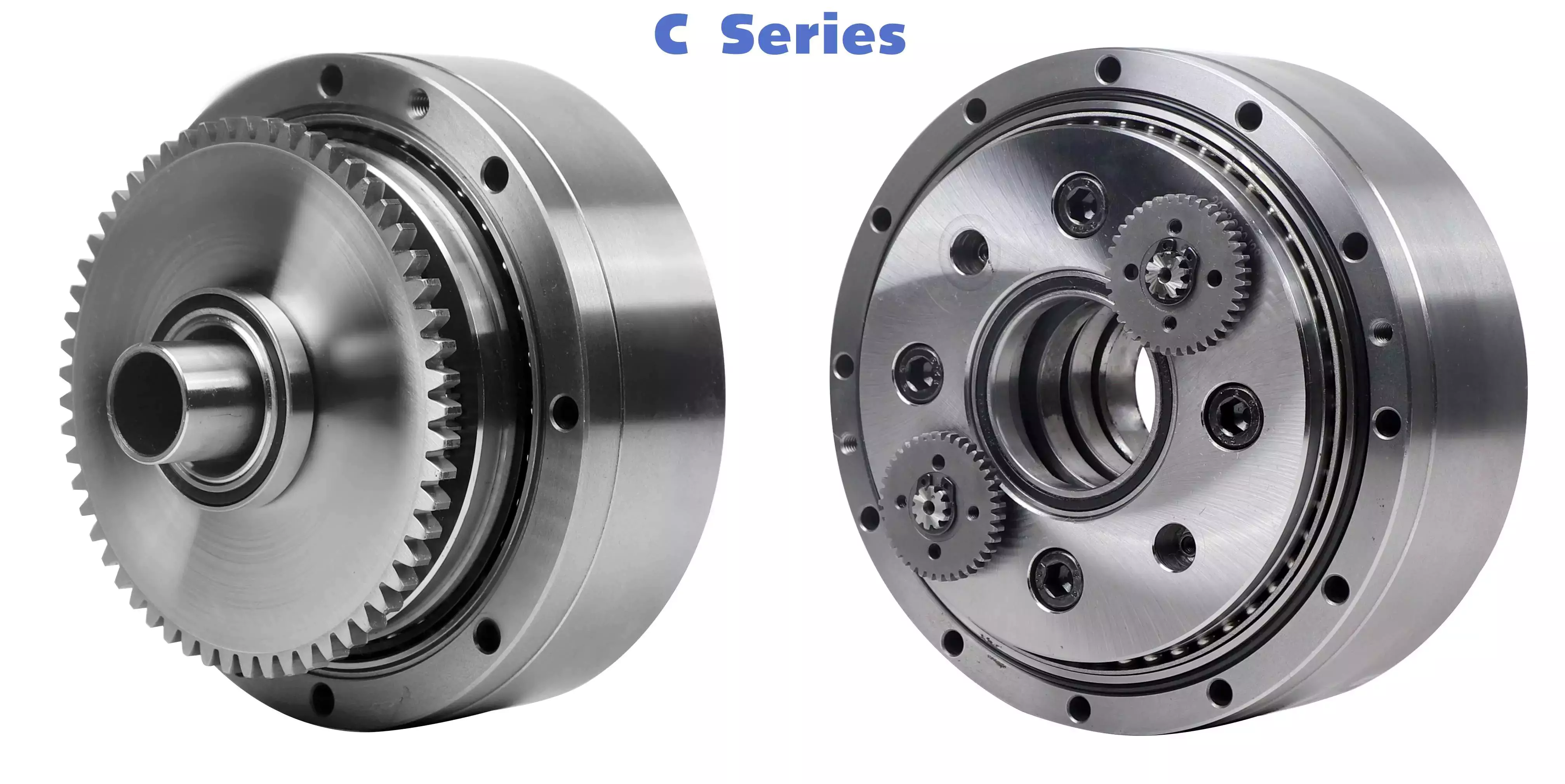
Involute gear tooth profile
Almost all gears use an involute gear tooth profile. This profile has a single curve, which means that the gear teeth do not have to be aligned closely with each other. This profile is smooth and can be manufactured easily.
Cycloid gears have a combination of epicycloid and hypocycloid curves. This makes them stronger than involute gear teeth. However, they can be more expensive to manufacture. They also have larger reduction ratios. They transmit more power than involute gears. Cycloid gears can be found in clocks.
When designing a gear, you need to consider several factors. Some of these include the number of teeth, the tooth angle and the lubrication type. Having a gear tooth that is not perfectly aligned can result in transmission error, noise and vibration.
The tooth profile of an involute gear is usually considered the best. Because of this, it is used in a wide variety of gears. Some of the most common applications for this profile are power transmission gears. However, this profile is not the best for every application.
Cycloid gears require more complex manufacturing processes than involute gear teeth. This can cause a larger tooth cost. Cycloid gears are used for less noisy applications.
Cycloid gears also transmit more power than involute gears. This can cause problems if the radii change tangentially. However, the shape is more simple than involute gears. Involute gears can handle centre sifts better.
Cycloid gears are less susceptible to transmission error. Cycloid gears have a convex surface, which makes them stronger than involute teeth. Cycloid gears also have a larger reduction ratio than involute gears. Cycloid teeth do not interfere with the mating teeth. However, they have a smaller number of teeth than involute teeth.
Rotation on the inside of the reference pitch circle of the pins
Whether a cycloidal gearbox is designed for stationary or rotating applications, the fundamental law of gearing must be observed: The ratio of angular velocities must be constant. This requires the rotation on the inside of the reference pitch circle of the pins to be constant. This is achieved through a series of cycloidal teeth, which act like tiny levers to transmit motion.
A cycloidal disc has N lobes which are rotated by three lobes per rotation around N pins. The number of lobes on a cycloidal disc is a significant factor in determining the transmission ratio.
A cycloidal disc is driven by an eccentric input shaft which is mounted to an eccentric bearing within an output shaft. As the input shaft rotates, the cycloidal disc moves around the pins of the pin disc.
The drive pin rotates at a 40 deg angle while the cycloidal disc rotates on the inside of the reference pitch circle of pins. As the drive pin rotates, it will slow the output motion. This means that the output shaft will complete only three revolutions with the input shaft, as opposed to nine revolutions with the input shaft.
The number of teeth on a cycloidal disc must be small compared to the number of surrounding pins. The disc must also be constructed with an eccentric radius. This will determine the size of the hole which will be required for the pin to fit between the pins.
When the input shaft is turned, the cycloidal disc will rotate on the inside of the reference pitch circle of roller pins. This will then transmit motion to the output shaft. The output shaft is supported by two bearings in an output housing. This design has low wear and torsional stiffness.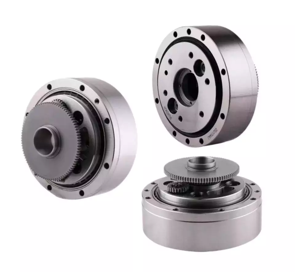
Transmission ratio
Choosing the right transmission ratio of cycloidal gearbox isn’t always easy. You might need to know the size of your gearbox before you can make an educated choice. You may also need to refer to the product catalog for guidance. For example, CZPT gearboxes have some unique ratios.
A cycloidal gear reducer is a compact and high-speed torque transmission device that reverses the direction of angular movement of the follower shaft. It consists of an eccentric cam positioned inside a cycloidal disc. Pin rollers on the follower shaft fit into matching holes in the cycloidal disc. In the process, the pins slide around the holes, in response to wobbling motion. The cycloidal disc is also capable of engaging the internal teeth of a ring-gear housing.
A cycloidal gear reducer can be used in a wide variety of applications, including industrial automation, robotics and power transmissions on boats and cranes. A cycloidal gear reducer is ideally suited for heavy duty applications with large payloads. They require specialized manufacturing processes, and are often used in equipment with precise output and high efficiency.
The cycloidal gear reducer is a relatively simple structure, but it does require some special tools. Cycloid gear reducers are also used to transmit torque, which is one of the reasons they are so popular in automation. Using a cycloidal gear reducer is a good choice for applications that require higher efficiency and lower backlash. It is also a good choice for applications where size is a concern. Cycloid gears are also a good choice for applications where high speed and high torque are required.
The transmission ratio of cycloidal gearbox is probably the most important function of a gearbox. You need to know the size of your gearbox and the type of gears it contains in order to make the right choice.
Vibration reduction
Considering the unique dynamics of a cycloidal gearbox, vibration reduction measures are required for a smooth operation. These measures can also help with the detection of faults.
A cycloidal gearbox is a gearbox with an eccentric bearing that rotates the center of the gears. It shares torque load with five outer rollers at any given time. It can be applied in many applications. It is a relatively inexpensive asset. However, if it fails, it can have significant economic impacts.
A typical input/output gearbox consists of a ring plate and two cranks mounted on the input shaft. The ring plate rotates when the input shaft rotates. There are two bearings on the output shaft.
The ring plate is a major noise source because it is not balanced. The cycloidal gear also produces noise when it meshes with the ring plate. This noise is generated by structural resonance. Several studies have been performed to solve this problem.
However, there is not much documented work on the condition monitoring of cycloidal gearboxes. In this article, we will introduce modern techniques for vibration diagnostics.
A cycloidal gearbox with a reduced reduction ratio has higher induced stresses in the cycloidal disc. In this case, the size of the output hole is larger and more material is removed from the cycloidal disc. This increase in the disc’s stresses leads to higher vibration amplitudes.
The load distribution along the width of the gear is an important design criterion. Using different gear profiles can help to optimize the transmission of torque. The contact stress of the cycloidal disc can also be investigated.
To determine the amplitude of the noise, the frequency of the gear mesh is multiplied by the shaft rate. If the RPM is relatively stable, the frequency can be used as a measure of magnitude. However, this is only accurate at close to failure.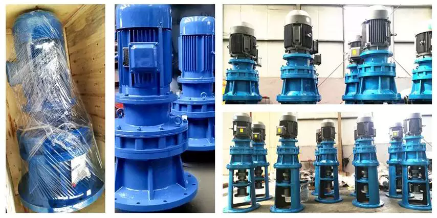
Comparison with planetary gearboxes
Several differences exist between cycloidal gearboxes and planetary gearboxes. They are related to gear geometry and manufacturing processes. Among them, there are:
– The output shaft of a cycloidal gearbox has a larger torque than the input shaft. The rotational speed of the output shaft is lower than the input shaft.
– The cycloid gear disc rotates at variable velocity, while the planetary gear has a fixed speed. Consequently, the cycloid disc and output flange transmission accuracy is lower than that of the planetary gears.
– The cycloidal gearbox has a larger gripping area than the planetary gear. This is an advantage of the cycloidal gearbox in that it can handle larger loads.
– The cycloid profile has a significant impact on the quality of contact meshing between the tooth surfaces. The width of the contact ellipses increases by 90%. This is a result of the elimination of undercuts of the lobes. In this way, the contact force on the cycloid disc is decreased significantly.
– The cycloid drive has lower backlash and high torsional stiffness. This allows a cycloidal drive to be more stable against shock loads. The cycloid drive is also a compact design, which is ideally suited for applications with large transmission ratios.
– The output hub of the cycloid gearbox has movable pins and rollers. These components are attached to the ring gear in the outer gearbox. The output shaft is also turned by the planet carrier. The output hub of the cycloid system is composed of two parts: the ring gear and the output flange.
– The input shaft of a cycloidal gearbox is connected to a servomotor. The input shaft is a cylindrical element that is fixed to the planet carrier.

editor by czh 2023-01-01
China Professional Qingdao OEM and ODM Tractor Gear Box with high quality
Merchandise Description
Evergreen Machinery’s Technology Phrases:
– Certification: ISO9001 & TS 16949 Certified
– Merchandise Content Regular: ISO, GB, ASTM, SAE, ISO, EN, DIN, JIS, BS
– Merchandise bodyweight variety: .05 kg ~ 1000kg
– Major process: Scorching forging, Chilly forging, Die forging…and so on
– Further Production Process: Deburring, Sandblasting, Machining, Warmth Treatment, Surface area treatment method, and so forth.
– Materials Offered:
– Carbon Metal: ten#, 15#, 20#, 25#, thirty#, 35#, 40#, forty five#, fifty#, 55#…etc.
– Alloy Steel: 15Mn, 16Mn, 40Cr, 42CrMo…and other alloy metal.
– Stainless Metal: SUS304, SUS316, SUS316L, and so forth
– Aluminum: 6061 T6, 6063 T6, 2A17
– Drawings: Second & 3D Drawings (Igs, PDF, JPEG, DWG, CAXA, UG, Stp…and many others.) could be created and offered based mostly on the samples.
Evergreen Machinery’s Tooling and Mould:
– CZPT existence: Semi-permanent
– Tooling Leadtime: two months, based on the structure and measurement
– Tooling & CZPT maintenance: Be dependable by CZPT Machinery
Evergreen Machinery’s Top quality manage:
– Defective goods rate: ≤ .1%.
– Quality Management: Sample and pilot operate will be offered one hundred% inspection for the duration of manufacturing and just before shipment, Sample examine for mass production according to ISO regular or customer needs
– Check equipment: Spectrum Analyzer, CMM, Hardness check equipment, Pressure check equipment
– After-revenue services: Accessible
– High quality scenario: Traceable
Why HangZhou CZPT Machinery?
– Prosperous experience: 25 years of encounter in casting and forging for European and U.S. marketplaces.
– OEM & ODM items application: Car components, Motor areas, Agriculture products elements, Teach elements, Valve, Pump… etc
– Material: 1> Grey Iron: HT100/HT150/HT200/HT250/HT300/HT350
2>Ductile Iron: QT400/QT450/QT500/QT600
– Materials Regular: ASTM, SAE, JIS, BS, DIN, ISO, GB
– Solution excess weight: .05kg ~1000kg
– Machining equipment: CNC, Lathe machine, Milling machine, Drilling equipment… and so forth
– Examination products: Optical Spectrum Analyzer, CMM, Hardness check tools, Tensile examination equipment
– Floor remedy: Blacking, Polishing, Anodize, Painting, Chrome plating, Zinc plating,Nickel plating, Tinting, Electrical power coating, E-coating… etc
– Utilized computer software for specification drawings: Professional/E, Auto CAD, Solidwork, CAXA, UG… and so on
– Additional obtainable process: Turning, reducing, milling, grinding, drilling, reaming, welding, stamping and threading
(forging workshop)
(Evergreen Machinery’s Patents)
What can CZPT Equipment supply, what tasks can you complete via us?
Our principal business in metallic merchandise, and our merchandise variety primarily handles Steel work, Aluminum Casting, Investment/Precision casting steel, Sand casting, Forging…and so forth.
These goods used in Wind electricity, Turbine, hefty obligation Truck, Prepare, Hydraulic Cylinder, Motor, Agriculture products, Lights, Marine and Mining machinery, Hardware, CZPT breeding, and many others.
(forging workshop)
Evergreen Machinery’s Functionality & Capacity:
– Capacity: 1>Al die casting: 3000~4000 ton per calendar year
2>Sand casting: 10000 ton for each year
3>Investment casting: 2000 ton for each year
4> Forging: 8000 ton per yr
– Certification: EN15085 & ISO3834 welding certification
– Machining products: CNC, Lathe machine, Milling machine, Drilling device, Grinding equipment… and so on
– Test tools: Optical Spectrum Analyzer, CMM, Hardness examination tools, Tensile examination machine
– Floor therapy: Powder coating, Anodization, Chrome plating, Painting, Sand blasting, Galvanization
(Uncooked Material Warehouse)
Evergreen Machinery’s Good quality & Service:
Evergreen Machinery’s good quality philosophy is “No Compromise“.
We have a varied customer selection CZPT above thirty countries and areas, Germany, United states of america, Australia & Japan are our major marketplaces. We’re fully commited to serve our consumer by supplying high quality goods and solutions. For our original consumers, we offer items and services that meet up with or exceed their anticipations whenever needed. For our emerging marketplace customers, we offer worth-included, cost-effective products every time attainable.
Welcome to go to CZPT Machinery (the photograph demonstrates the customer and our standard supervisor Walt Wang)
Who We Serve? You are our high quality customer!
The Programs of Our OEM Customized Metal Parts Engine components, Auto elements, Machinery Parts, Rail Prepare elements, Truck Components,Tractor Parts, Construction Equipment, Agriculture Tools,Other industrial fields.
(Fantastic cooperation with Canadian Partner!)
(Great cooperation with Russian Partner!)
Evergreen Machinery’s FAQ:
Q: Do you make personalized items or completed components?
A: Sure,all areas are not in stock, custom produced according to customer’s drawings or samples! If you have any areas to be made, please feel cost-free to deliver your drawings/samples to us.
Q: Will my drawing be safe right after you get it?
A: Sure, we will not launch your design to 3rd celebration until with your permission. And we can sign the NDA ahead of you send out the drawing.
Q: What is the MOQ?
A: Typically we will not have a MOQ, but the far more, the more affordable. In addition to, we are satisfied to make prototype part or sample for consumers to ensure quality common.
Q: Whether or not some samples can be supplied?
A: Of course, just want some sample value, we will return it back when proceed into mass manufacturing. If a molded is necessary, we will cost the mould price prior to beginning. Then the mildew belongs to customer.
Q: What’s your items assortment?
A: OEM & ODM items range: Auto areas, Truck Elements, Engine areas, Agriculture products parts, Prepare elements, Components, and so forth.
Q: What is actually machining devices do you have?
A: CNC, Lathe machine, Milling device, Drilling device, and so on
Q: Do you have any test equipment?
A: Optical Spectrum Analyzer, CMM, Hardness take a look at equipment, Tensile take a look at equipment
Q: How to deal with it when they are located to be in inadequate top quality?
A: Please rest assured that all our products are QC inspected and approved with inspection report ahead of shipping and generally there will be no non-conformance in circumstance of non-conformance, please get in touch with us right away, get some photos or films, we will check out the issues and have them reworked or fixed or replaced at the initial time, the ensuing transportation fees will be borne by our company.
| PROCESS TYPE | MATERIAL | STANDARD | |
| Sand Casting | Green Sand | Grey Iron, Ductile Iron, Malleable Iron, Brass, Bronze | ISO GB ASTM SAE BS JIS DIN |
| Furan Resin Sand | |||
| Cold Harden Resin Sand | |||
| Investment casting | Water galss casting | Stainless Steel, Carbon Steel, Special Alloy Steel Bronze, Brass, Aluminum | |
| Lost wax casting | |||
| Forging | Hot Forging | Stainless Steel, Carbon Steel, Alloy Streel, Brass, Aluminum | |
| Warm Forging | |||
| Cold Forging | |||
| Machining and other further processiong | Stamping, cutting, welding, polishing,sand blasting…… | All metal material | |
The Different Types of Gearboxes
There are many different types of gearboxes. Some brands have more than one type. In this article, we’ll discuss the planetary gearbox, the worm reduction gearbox, the shaft mounted gearbox, and the one speed gearbox. This article will also help you determine which type of gearbox is best for your vehicle. And don’t worry if you don’t know the terminology yet. We’ll explain each type in detail so that you know what you’re getting yourself into.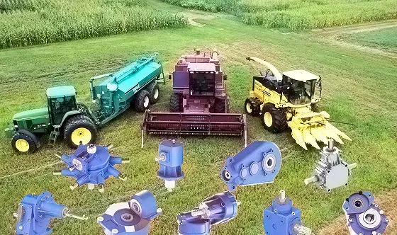
Planetary gearbox
Planetary gears have many advantages. The multiple gears in a planetary gearbox mesh simultaneously during operation. As such, they provide high efficiency and transmit high transmittable torque. These gears are widely used in various industries and are resistant to high shock loads and demanding conditions. CZPT is one of the companies that offer planetary gearboxes. Its products do not require special tools for assembly, and its scalable design minimizes safety stock.
Among the numerous benefits of planetary gearing is its compactness and lightweight. As such, it is suitable for wide applications with space and weight constraints. However, to truly appreciate its benefits, it is necessary to understand its mechanisms. Here are some of the most common details about planetary gearing:
The planetary gearbox has two mounted gears: an input shaft and an output shaft. Each gear has multiple teeth that are attached to a carrier and rotate with the input shaft. The carrier is connected to the output shaft. A planetary gear is mounted on both gears via a carrier. The carrier rotates in order to drive the planetary gear. The sun gear is often the input gear. The other gear is called the outer gear.
Planetary gearboxes are highly customizable. The size, mounting, and housing options vary, as do the reduction ratios and input speeds. Different types can be manufactured for different applications and include options such as electrical or mechanical preload. The final design of a planetary gearbox can be highly customized, based on the specifications of the application. By combining engineering excellence and ongoing innovation, planetary gearboxes provide years of trouble-free operation.
A planetary gearbox can be either an electric motor or a manual one. The latter has more features than the former, and can be used in applications where space is an issue. The primary features of a planetary gearbox include its backlash, torque, and ratio. Secondary features include noise, corrosion resistance, and construction. A planetary gearbox is a highly versatile gearbox that can drive anything from simple machinery to advanced electrical systems.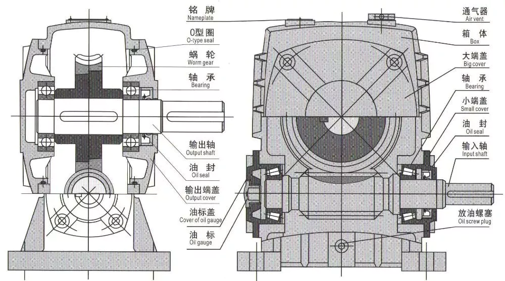
Worm reduction gearbox
The global worm reduction gearbox market report compiles key insights from the industry to help you improve your business strategy. This report will help you create a comprehensive business document that will enhance your company’s competitive edge. To obtain this report, visit our website now! Read our latest report to find out what you can expect from the global worm reduction gearbox market. Alternatively, request a sample copy for more details. Here is a sneak peek of the report:
Worm gears are made with different thread counts and are usually not matched with the CZPT standard. In general, a single thread worm should be used with a single thread worm. Worm gears have either right or left threads, and their thread count will be different as well. This type of gear is used to reduce the speed of a rotating shaft. The speed reduction ratio will be about 50 percent if the worms have the same thread count as the CZPT gears.
The standard gear set transfers power at the peak load point of a tooth, called the pitchline. The worm gear moves slowly against the wheel’s metal surface. The worm gear is also more complex than the standard gear because the worm is sliding rather than rolling. Worm gears are hard to lubricate. Moreover, the sliding contact between the gear and worm increases the complexity of the gear set. They can be a great solution for applications where noise is a significant factor.
The axial pitch and circular pitch of the worm are equal. The ratio of these two indices determines the speed of transmission. For a worm reduction gearbox to work, the axial pitch and the circular pitch must match. The pitch angle of a worm can either be left-handed or right-handed. The lead of a worm is the distance one thread travels in one revolution. The lead angle is the angle tangent to the thread helix of the cylinder’s pitch. When a worm mesh is reversed, the majority of the mesh will be on the receding arc.
Worm gears generate more heat than their counterparts, so it is important to choose a worm reduction gearbox carefully. You will want to choose the material and amount of lubricating oil carefully. Worm gears are generally made of tin bronze. The paired worms are hardened to HRC45-55. In general, they are durable, lasting up to ten years. But they will wear out – and they wear out – so you may want to consider some other factors.
Shaft-mounted gearbox
Shaft-mounted gearboxes are designed for a variety of mining and quarry applications. Their high reliability and low maintenance make them an excellent choice in these types of applications. Shaft-mounted gearboxes also feature an optional backstop device that prevents the unit from rotating in one direction. This makes them an excellent choice for applications where alignment accuracy is an issue. Here are some of the benefits of using a shaft-mounted gearbox:
Shaft-mounted gearboxes are typically constructed of aluminium, and come in sizes ranging from 050 to 125. They feature a variety of reduction ratios and ensure optimum efficiency in all operating conditions. New S series sizes, 140 and 150, extend the application range of shaft-mounted gearmotors. They are both backed by a two-year warranty. For even greater peace of mind, Shaft-mounted gearboxes are available with a range of warranty options.
The most common applications for a Shaft-mounted gearbox include traction-driven applications where a low-speed shaft is required for operation. They also are suitable for applications without a foundation, where the motor is mounted next to the reducer. To prevent the gear drive from rotating, a torque arm is attached between the motor and the shaft. Small-sized shaft-mounted gear drives are usually made without motor mount kits, which can make them an excellent choice for conveying light loads.
Another important feature of a Shaft-mounted gearbox is its mounting position. The reduced motion through the drive is redirected through the shaft, creating additional forces. These additional forces can affect the performance of the gearbox, causing vibrations and noise. Consequently, it is important to replace worn or damaged belts on a regular basis. Further, shaft-mounted gearboxes can be affected by problems with other components and amplify vibrations.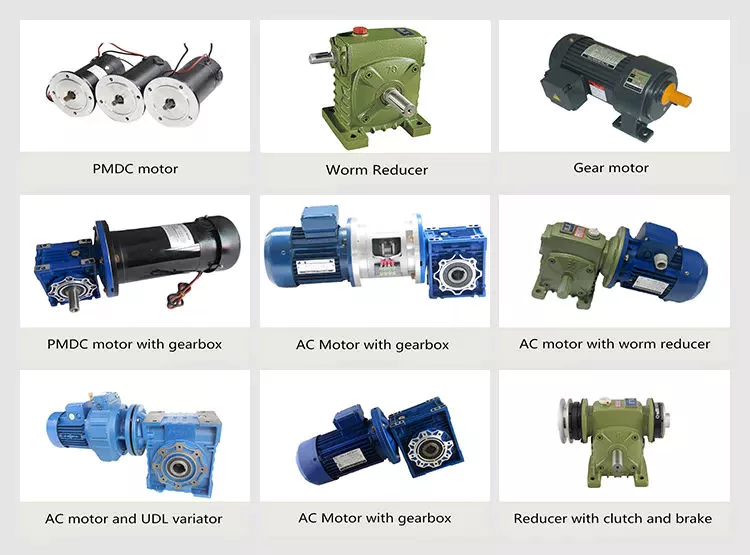
1 speed gearbox
CZPT Group Components produces one speed gearboxes. These transmissions are produced in the CZPT Group’s Kassel plant. They are compact and robust, and are designed for easy integration. The Bosch Rexroth GD1 one-speed gearbox is easy to install horizontally or vertically. The Plug and Drive system integrates the gearbox with the existing cooling system. There are many other benefits to this gearbox.
With an ID.3 electric drive motor, the maximum torque is delivered at 16,000 rpm. This single-speed transmission offers high power density and excellent noise-reduction, making it ideal for electric vehicles. The e-drive motor is extremely quiet and requires precision manufacturing. The e-drive motor also enables a wide range of driving conditions. It can reverse when needed, and reaches its maximum speed at 16,000.
The single-speed gearbox is a standard feature on most electric vehicles. Some electric vehicles, such as the Porsche Taycan, will be equipped with a two-speed gearbox. This gearbox offers more top speed and range, but it is more complex than a standard single-speed gearbox. CZPT doesn’t need to add complexity to its electric vehicles. After all, a 355 horsepower family wagon is not likely to need a dual-speed gearbox.
In addition to simplifying the transmission, the patent claims also address improvements in structural design. Fig. 5 shows a schematic representation of a transmission 50′, wherein gear sets Z1 and Z4 are exchanged between partial transmissions. This switch matrix also reflects the synchronized gears and lastshelf gears. Hydraulically betatigte Lamellenkupplungen (HBA) also form a last-shelf gear.
Another advantage of the patent claim is that it offers numerous functional freedoms, which is especially valuable in the design of an automobile. One of the patent claims identifies a tosatzlicher middle gear that allows a driver to switch between second and third gears, with a single gearbox. In a conventional one-speed transmission, the tosatzlicher middle gear is attached to the second and first part gearbox. The latter has a second and third gear.

