Product Description
GRH specialized in providing hydraulic components and solutions for hydraulic systems.
With continuous improvement and enthusiasm over the past 30 years, CZPT has developed into an emerging power in the fluid power industry since it was established in 1986.
GRH (ZheJiang ) – International Sales Office
GRH (ZheJiang ) – Manufacturing Facility and Domestic Sales Office
—————————————————————————————————————————————————
Production description
| We can produce motor according to your needs ! |
About Us
Application and Partners
Contact us!
| Application: | Motor, Machinery, Agricultural Machinery |
|---|---|
| Hardness: | Hardened Tooth Surface |
| Installation: | Vertical Type |
| Layout: | Expansion |
| Gear Shape: | Conical – Cylindrical Gear |
| Step: | Stepless |
| Samples: |
US$ 1050/Piece
1 Piece(Min.Order) | |
|---|
| Customization: |
Available
| Customized Request |
|---|
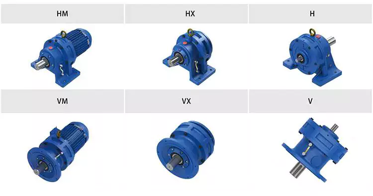
How to Use a Cyclone Gearbox
Often, a cycloidal gearbox is used in order to achieve a torque transfer from a motor or pump. This type of gearbox is often a common choice as it has a number of advantages over a regular gearbox. Its main advantage is that it is easy to make, which means that it can be incorporated into a variety of applications. However, if you want to use a cycloidal gearbox, there are a few things that you need to know. These include the operation principle, the structure and the dynamic and inertial effects that come with it.
Dynamic and inertial effects
Several studies have been carried out on the static and dynamic properties of cycloidal gears. The study of these effects is beneficial in assisting optimal design of cycloidal speed reducers.
In this paper, the dynamic and inertial effects of a two-stage cycloidal speed reducer have been investigated using the CZPT program package. Moreover, a new model for cycloidal reducers based on non-linear contact dynamics has been developed. The new model aims to predict several operational conditions.
The normal excitation contact force for the cycloid discs of the first and second stage is very similar. However, the total deformation at the contact point is different. This effect is mainly due to the system’s own oscillations. The cycloid discs of the second stage turn around the ring gear roller with a 180deg angle. This angle is a significant contributor to the torque loads. The total excitation force on the cycloid discs of first and second stage is 1848 N and 2068.7 N, respectively.
In order to analyze the contact stress, different gear profiles were investigated. The mesh density was considered as an important design criterion. It was found that a bigger hole reduces the material content of the cycloidal disc and results in more stresses.
Moreover, it is possible to reduce the contact forces in a more efficient manner by changing the geometric parameters. This can be done by mesh refinement along the disc width. The cycloidal disc has the greatest influence on the output results.
The efficiency of a cycloidal drive increases with the increase in load. The efficiency of a cycloidal reducer also depends on the eccentricity of the input shaft and the cycloidal plate. The efficiency curve for small loads is linear. However, for the larger loads, the efficiency curve becomes more non-linear. This is because the stiffness of the cycloid reducer increases as the load increases.
Structure
Despite the fact that it looks like a complicated engineering puzzle, the construction of a cycloidal gearbox is actually quite simple. The key elements are the base, the load plate and the thrust bearing. All these elements work together to create a stable, compact gearbox.
The base is a circular section with several cylindrical pins around its outer edge. The pins are fixed on a fixed ring that holds them in a circular path. The ring serves as a reference circle. The circle’s size is approximately 5mm in diameter.
The load plate is a series of threaded screw holes. These are arranged 15mm away from the center. These are used to anchor external structures. The load plate must be rotated around the X and Y axis.
The thrust bearing is placed on top of the load plate. The bearing is made of an internal diameter of 35mm and an external diameter of 52mm. It is used to allow rotation around the Z axis.
The cycloidal disc is the centerpiece of the cycloidal gearbox. The disc has holes for the pins that drive the output shaft. The holes are larger than those used in output roller pins. The disc also has a reduced eccentricity.
The pins are attached to the cycloidal disc by rolling pins. The pins are made of a material that provides mechanical support for the drive during high-torque situations. The pins have a 9mm external diameter. The disc has a number of lobes and is rotated by one lobe per shaft revolution.
The cycloidal gearbox also has a top cover that helps keep the components together. The cover has a pocket for tools. The top cover also has threads that screw into the casing.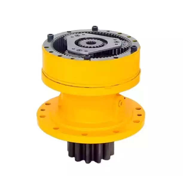
Operation principle
Among many types of gear transmissions, cycloidal gearboxes are used in heavy machinery and multi-axis robots. They are highly effective, compact and capable of high ratios. In addition, they have an overload capability.
Cycloid disks are driven by eccentric shafts that rotate around fixed ring pins. Roller pins of the pin disc engage with holes in the cycloidal disc. These roller pins drive the pin disc and the pin disc transfers the motion to the output shaft.
Unlike conventional gear drives, cycloidal drives have low backlash and high torsional stiffness. They are ideally suited to heavy loads and all drive technologies. The lower mass and compact design of the cycloidal disk also contributes to its high efficiency and positioning accuracy.
The cycloidal disc plays a central role in the gearbox kinematics. It rotates around a fixed ring in a circle. When the disc is pushed against the ring gear, the pins engage with the disc and the roller pins rotate around the pins. This rotating motion generates vibration, which travels through the driven shafts.
Cycloid discs are typically designed with a short cycloid, so that the eccentricity is minimized. This reduces unbalance forces at high speeds. Ideally, the number of lobes on the cycloid is smaller than the number of surrounding pins. This reduces the amount of Hertzian contact stress.
Unlike planetary gears, cycloidal gears have high accuracy and are capable of withstanding shock loads. They also experience low friction and less wear on tooth flanks. They also have higher efficiency and load capacity.
Cycloid gears are generally more difficult to manufacture than involute gears. Cycloid gears are not suitable for stacking gear stages. They require extreme accuracy for manufacturing. However, their smaller size and low backlash, high torsional stiffness, and low vibration make them ideal for use in heavy machines.
Involute gear tooth profile
Almost all gears are manufactured with an involute gear tooth profile. Cycloid gears are also produced with this profile. Compared with involute gears, cycloid gears are stronger and can transmit more power. However, they can also be more difficult to manufacture. This makes them costlier.
The involute gear tooth profile is a smooth curve. It is derived from the involute curve of a circle. A tangent to the base circle is the normal at any point of an involute.
This curve has properties that allow the involute gear teeth to transfer motion in perpendicular direction. It is also the path traced by the end of the string unwrapping from a cylinder.
An involute profile has the advantage of being easy to manufacture. It also allows for smooth meshing despite misalignment of the centre distance. This profile is also preferred over a cycloid tooth profile, but it is not the best in every regard.
Cycloid gear teeth are also made of two curves. Unlike involute teeth, cycloid gear teeth have a consistent radius. Cycloid gears are less likely to produce noise. But they are also more expensive to manufacture.
Involute teeth are easier to manufacture because they have only one curve. Cycloid gears can also be made with a rack type cutter. This makes them cheaper to manufacture. However, they require an expert design. They can also be manufactured with a gear shaper that includes a pinion cutter.
The tooth profiles that satisfy the law of gear-tooth action are sometimes called conjugate profiles. The involute profile is the most common of these. It allows for constant torque transmission.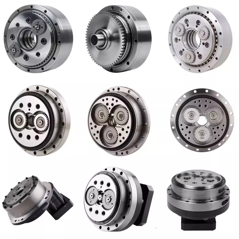
Backlash
Typically, cycloidal drives provide a high ratio of transmission with no backlash. This is because the cycloid disc is driven by an eccentric shaft. During rotation, the cycloid disc rotates around a fixed ring. This ring also rotates independently of the center of gravity.
The cycloid disc is typically shortened to reduce the eccentricity. This helps to minimize the unbalance forces that may occur at high speeds. The cycloid also offers a larger gear ratio than traditional gears. This provides a better positional accuracy.
Cycloid drives also have a high torsional stiffness. This provides greater torsional resilience and shock load capabilities. This is important for a number of reasons, such as in heavy-duty applications.
Cycloid drives also have lower mass. These benefits make them ideally suited for all drive technologies. The design also allows for higher torsional stiffness and service life. These drives also have a much smaller profile.
Cycloid drives are also used to reduce speed. Because of the high torsional stiffness of the cycloid, they also have high positioning accuracy.
Cycloid drives are well-suited to a variety of applications, including electric motors, generators, and pump motors. They are also highly resistant to shock loads, which is important in a variety of applications. This design is ideal for applications that require a large transmission ratio in a compact design.
Cycloid drives also have the advantage of minimizing the clearance between the mating components. This helps to eliminate interference and ensure a positive fit. This is particularly important in gearboxes. It also allows for the use of a load cell and potentiometer to determine the backlash of the gearbox.

editor by CX 2023-11-22
China High Torque Precision Robot Arm Joint Rv Gearbox Reducer Cycloidal pin wheel harmonic Reduction Gear comer gearbox
Guarantee: 1 12 months
Relevant Industries: Other
Fat (KG): 35
Tailored assistance: OEM, ODM, OBM
Gearing Arrangement: Worm
Output Torque: 10 N.M–55mm and slowly realize the smart tools creation line .Our merchandise are commonly used in textile machine、printing machine、food machine、medical machine、convey machine、packaging machinery、work master machine、vending machine、 cement machine、computer flat knitting machine、automatic table、office gear and photo voltaic photovoltaic tools etc .Our items are popularly offered in domestic marketplaces and overseas marketplaces such as Southeast Asia、 India、Europe、America、Middle East and Australia and so forth. The revenue quantity proceeds to increase at a charge of much more than 40% for every yearWe passed ISO9001、CE 、UL、CCC and ROHS certification and so on..We can satisfy you with the industry’s first technologies ,good quality and rapidly provider assist .Sincere cooperation with you to build gorgeous Backyard .Welcome to go to our manufacturing facilityHangZhou HENGTUO MOTOR CO.,LTDADD: N0.108,SHANGYEJIA Road NORTH,HUSHAN Road, HangZhou,HangZhou City,ZHangZhouG PROVINCE,CHINA. Certifications FAQ Q: Are you equipment motors company ?A: Sure we are manufacturing facility.Q: Where are your factory ?A: HangZhou, HangZhou, Around ZheJiang cityQ: How numerous worker in your manufacturing facility ?A: 158 employees.Q: How to purchase?A: Send us inquiry → Get our quotation → Negotiate information → Validate the sample → Sign agreement/deposit → Mass production→Cargo ready → Balance/delivery → Even more cooperationQ: How about Sample buy?A: Sample is offered for you. please make contact with us for details. When we cost you sample price, please really feel simple, it would be refundwhen you spot formal purchase.Q: Which ship way is available?A: DHL, UPS, FedEx, TNT, EMS, China Post,Sea are offered.The other shipping techniques are also offered, please speak to us if youneed ship by the other delivery way. Q: How long is direct time ?A: Produce time is dependent on the amount you buy. normally lead time requires 3-5 doing work days.
How to Select a Gearbox
When you drive your vehicle, the gearbox provides you with traction and speed. The lower gear provides the most traction, while the higher gear has the most speed. Selecting the right gear for your driving conditions will help you maximize both. The right gearing will vary based on road conditions, load, and speed. Short gearing will accelerate you more quickly, while tall gearing will increase top speed. However, you should understand how to use the gearbox before driving.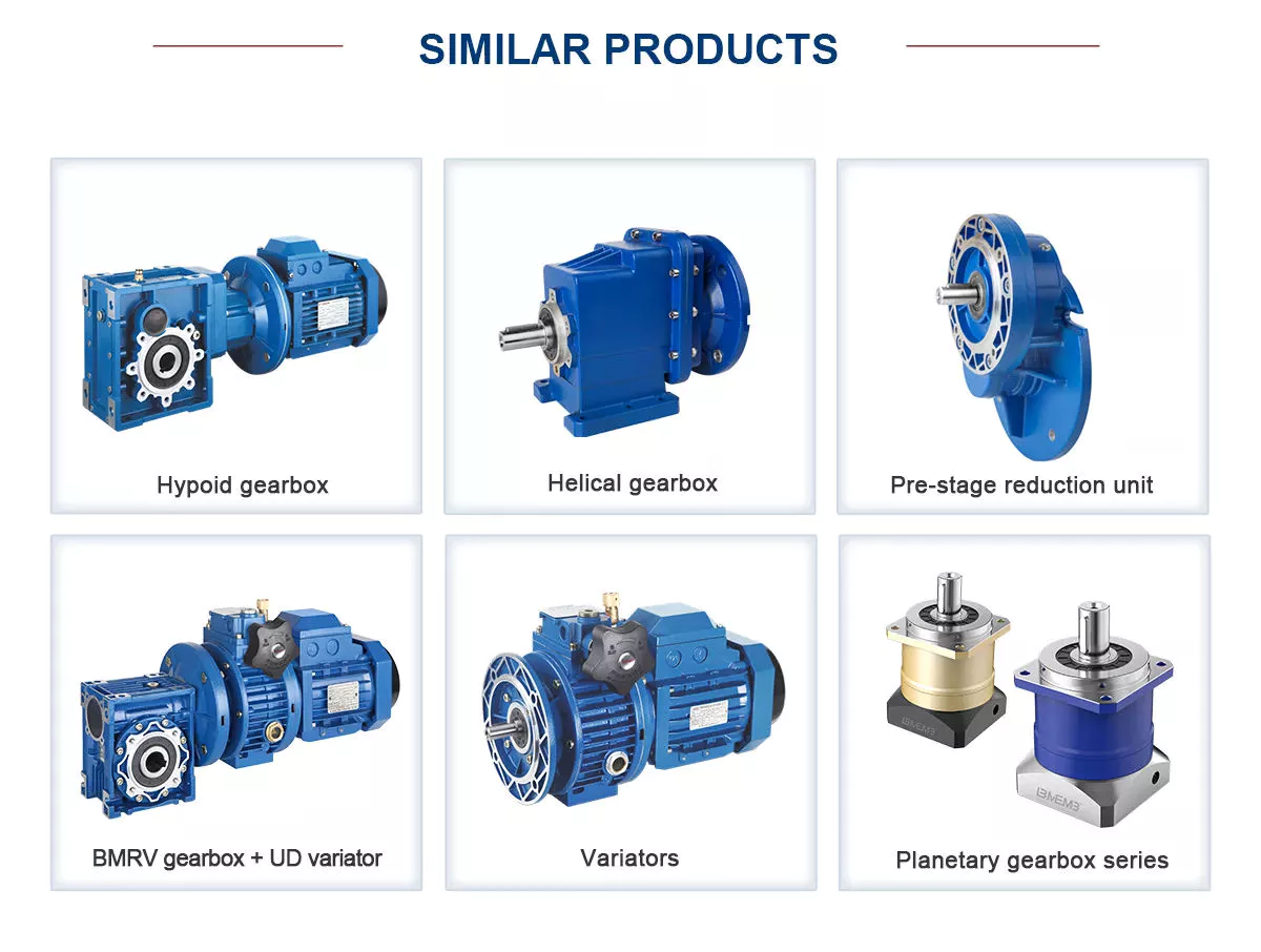
Function
The function of the gearbox is to transmit rotational energy to the machine’s drive train. The ratio between input and output torque is the ratio of the torque to the speed of rotation. Gearboxes have many different functions. A gearbox may have multiple functions or one function that is used to drive several other machines. If one gear is not turning, the other will be able to turn the gearbox. This is where the gearbox gets its name.
The pitch-controlled system has an equal number of failure modes as the electrical system, accounting for a large proportion of the longest machine downtime and halt time. The relationship between mechanisms and faults is not easily modeled mathematically. Failure modes of gearboxes are shown in Fig. 3. A gearbox’s true service life is six to eight years. However, a gearbox’s fault detection process must be developed as mature technology is required to reduce the downtime and avoid catastrophic incidents.
A gearbox is a vital piece of machinery. It processes energy produced by an engine to move the machine’s parts. A gearbox’s efficiency depends on how efficiently it transfers energy. The higher the ratio, the more torque is transferred to the wheels. It is a common component of bicycles, cars, and a variety of other devices. Its four major functions include:
In addition to ensuring gearbox reliability, a gearbox’s maintainability should be evaluated in the design phase. Maintainability considerations should be integrated into the gearbox design, such as the type of spare parts available. An appropriate maintenance regime will also determine how often to replace or repair specific parts. A proper maintenance procedure will also ensure that the gearbox is accessible. Whether it is easy to access or difficult to reach, accessibility is essential.
Purpose
A car’s transmission connects the engine to the wheels, allowing a higher-speed crankshaft to provide leverage. High-torque engines are necessary for the vehicle’s starting, acceleration, and meeting road resistance. The gearbox reduces the engine’s speed and provides torque variations at the wheels. The transmission also provides reversing power, making it possible to move the vehicle backwards and forwards.
Gears transmit power from one shaft to another. The size of the gears and number of teeth determine the amount of torque the unit can transmit. A higher gear ratio means more torque, but slower speed. The gearbox’s lever moves the engaging part on the shaft. The lever also slides the gears and synchronizers into place. If the lever slips to the left or right, the engine operates in second gear.
Gearboxes need to be closely monitored to reduce the likelihood of premature failure. Various tests are available to detect defective gear teeth and increase machine reliability. Figure 1.11(a) and (b) show a gearbox with 18 teeth and a 1.5:1 transmission ratio. The input shaft is connected to a sheave and drives a “V” belt. This transmission ratio allows the gearbox to reduce the speed of the motor, while increasing torque and reducing output speed.
When it comes to speed reduction, gear box is the most common method for reducing motor torque. The torque output is directly proportional to the volume of the motor. A small gearbox, for example, can produce as much torque as a large motor with the same output speed. The same holds true for the reverse. There are hybrid drives and in-line gearboxes. Regardless of the type, knowing about the functions of a gearbox will make it easier to choose the right one for your specific application.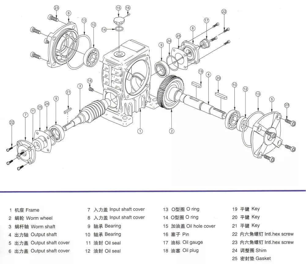
Application
When selecting a gearbox, the service factor must be considered. Service factor is the difference between the actual capacity of the gearbox and the value required by the application. Additional requirements for the gearbox may result in premature seal wear or overheating. The service factor should be as low as possible, as it could be the difference between the lifetime of the gearbox and its failure. In some cases, a gearbox’s service factor can be as high as 1.4, which is sufficient for most industrial applications.
China dominates the renewable energy industry, with the largest installed capacity of 1000 gigawatts and more than 2000 terawatt hours of electricity generated each year. The growth in these sectors is expected to increase the demand for gearboxes. For example, in China, wind and hydropower energy production are the major components of wind and solar power plants. The increased installation capacity indicates increased use of gearboxes for these industries. A gearbox that is not suitable for its application will not be functional, which may be detrimental to the production of products in the country.
A gearbox can be mounted in one of four different positions. The first three positions are concentric, parallel, or right angle, and the fourth position is shaft mount. A shaft mount gearbox is typically used in applications where the motor can’t be mounted via a foot. These positions are discussed in more detail below. Choosing the correct gearbox is essential in your business, but remember that a well-designed gearbox will help your bottom line.
The service factor of a gearbox is dependent on the type of load. A high shock load, for example, can cause premature failure of the gear teeth or shaft bearings. In such cases, a higher service factor is required. In other cases, a gearbox that is designed for high shock loads can withstand such loads without deteriorating its performance. Moreover, it will also reduce the cost of maintaining the gearbox over time.
Material
When choosing the material for your gearbox, you must balance the strength, durability, and cost of the design. This article will discuss the different types of materials and their respective applications and power transmission calculations. A variety of alloys are available, each of which offers its own advantages, including improved hardness and wear resistance. The following are some of the common alloys used in gears. The advantage of alloys is their competitive pricing. A gear made from one of these materials is usually stronger than its counterparts.
The carbon content of SPCC prevents the material from hardening like SS. However, thin sheets made from SPCC are often used for gears with lower strength. Because of the low carbon content, SPCC’s surface doesn’t harden as quickly as SS gears do, so soft nitriding is needed to provide hardness. However, if you want a gear that won’t rust, then you should consider SS or FCD.
In addition to cars, gearboxes are also used in the aerospace industry. They are used in space travel and are used in airplane engines. In agriculture, they are used in irrigation, pest and insect control machinery, and plowing machines. They are also used in construction equipment like cranes, bulldozers, and tractors. Gearboxes are also used in the food processing industry, including conveyor systems, kilns, and packaging machinery.
The teeth of the gears in your gearbox are important when it comes to performance. A properly meshing gear will allow the gears to achieve peak performance and withstand torque. Gear teeth are like tiny levers, and effective meshing reduces stress and slippage. A stationary parametric analysis will help you determine the quality of meshing throughout the gearing cycle. This method is often the most accurate way to determine whether your gears are meshing well.
Manufacturing
The global gear market is divided into five key regions, namely, North America, Europe, Asia Pacific, and Latin America. Among these regions, Asia Pacific is expected to generate the largest GDP, owing to rapidly growing energy demand and investments in industrial infrastructure. This region is also home to some of the largest manufacturing bases, and its continuous building of new buildings and homes will support the industry’s growth. In terms of application, gearboxes are used in construction, agricultural machinery, and transportation.
The Industrial Gearbox market is anticipated to expand during the next several years, driven by the rapid growth of the construction industry and business advancements. However, there are several challenges that hamper the growth of the industry. These include the high cost of operations and maintenance of gear units. This report covers the market size of industrial gearboxes globally, as well as their manufacturing technologies. It also includes manufacturer data for the period of 2020-2024. The report also features a discussion of market drivers and restraints.
Global health crisis and decreasing seaborne commerce have moderately adverse effects on the industry. Falling seaborne commerce has created a barrier to investment. The value of international crude oil is expected to cross USD 0 by April 2020, putting an end to new assets development and exploitation. In such a scenario, the global gearbox market will face many challenges. However, the opportunities are huge. So, the market for industrial gearboxes is expected to grow by more than 6% by 2020, thanks to the increasing number of light vehicles sold in the country.
The main shaft of a gearbox, also known as the output shaft, spins at different speeds and transfers torque to an automobile. The output shaft is splined so that a coupler and gear can be connected to it. The counter shaft and primary shaft are supported by bearings, which reduce friction in the spinning element. Another important part of a gearbox is the gears, which vary in tooth count. The number of teeth determines how much torque a gear can transfer. In addition, the gears can glide in any position.


editor by czh 2023-02-16